Topic orthographic drawing autocad: Unlock the potential of AutoCAD with our comprehensive guide on orthographic drawing, a foundational skill set for drafting professionals and enthusiasts alike, designed to enhance your designs with precision and efficiency.
Table of Content
- How do I create an orthographic drawing in AutoCAD?
- Understanding Orthographic Drawing in AutoCAD
- Steps to Create an Orthographic View in AutoCAD
- Orthographic Drawing Techniques and Parameters
- Ortho Tracking for Precision in AutoCAD
- Creating and Projecting 3-View Orthographic Projections
- Utilizing Ortho and Polar Tracking for Enhanced Drafting Efficiency
- YOUTUBE: AutoCAD Orthographic Projection Example 1 - Multi View Drawing
- Advanced Tools and Techniques in Orthographic Drawing
- Orthographic Projections: Standards and Symbols
How do I create an orthographic drawing in AutoCAD?
To create an orthographic drawing in AutoCAD, you can follow these steps:
- Open AutoCAD on your computer.
- Create a new drawing or open an existing one.
- Ensure that you have the necessary objects or components to include in your orthographic drawing.
- Decide on the views you want to include in your drawing, such as front, top, and side views.
- Go to the \"View\" tab in the AutoCAD ribbon menu.
- In the \"Create\" panel, click on the \"Orthographic\" button.
- Select the desired view from the drop-down list, such as \"Front\" or \"Top\".
- AutoCAD will automatically generate the orthographic projection of the selected view on the drawing.
- Repeat steps 6 and 7 for each additional view you want to include in your drawing.
- You can adjust the scale and position of the views as necessary using AutoCAD\'s editing tools.
- Add dimensions, labels, and any other annotations to complete your orthographic drawing.
- Save your drawing to a location on your computer.
By following these steps, you should be able to create an orthographic drawing using AutoCAD.
READ MORE:
Understanding Orthographic Drawing in AutoCAD
Orthographic drawing is a cornerstone of technical drafting, enabling the precise representation of 3D objects in two dimensions. AutoCAD, a leading CAD software, offers robust tools for creating orthographic drawings, essential for engineers, architects, and designers. This section delves into the fundamentals and advanced techniques of orthographic drawing in AutoCAD, guiding you through the creation process, from setup to execution.
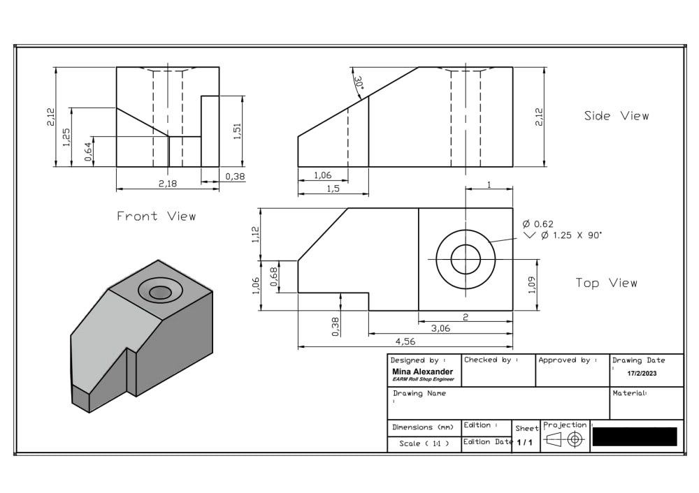
- Introduction to Orthographic Projection: Understand the principles of orthographic projection, which includes front, top, and side views to represent the dimensions and shape of an object accurately.
- Setting Up Your Drawing: Learn how to prepare your AutoCAD workspace, including setting the correct unit system, drawing limits, and layer properties for an efficient drawing process.
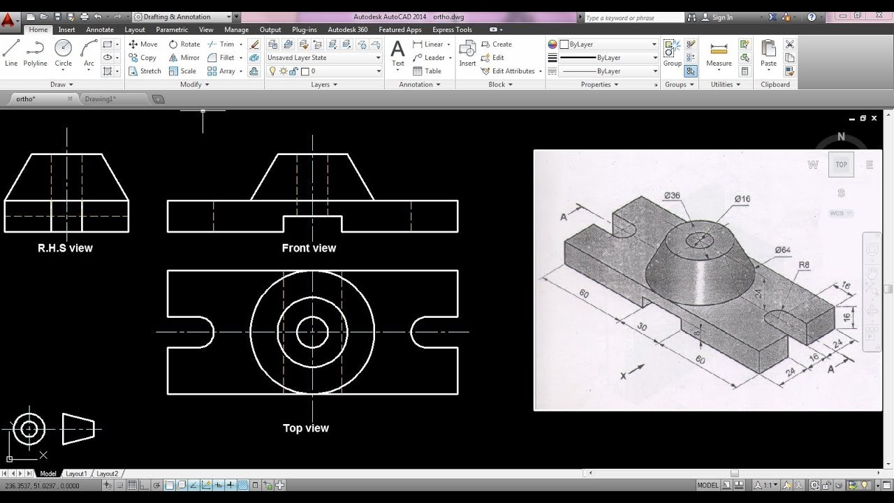
- Drawing Views: Detailed steps on creating the three primary views (front, top, side) using AutoCAD commands and tools, ensuring alignment and scale accuracy.
- Adding Details and Dimensions: Techniques for adding critical details, dimensions, and annotations to your orthographic drawings, enhancing clarity and understanding.
- Advanced Orthographic Projection Techniques: Explore advanced methods such as auxiliary views and sectioning for complex objects, providing a deeper insight into the object’s features.
- Utilizing Layers and Styles: Best practices for using layers, text styles, and dimension styles to organize and standardize your drawings for professional use.
By mastering orthographic drawing in AutoCAD, you can create detailed, accurate representations of physical objects, essential for manufacturing, construction, and design projects. The following sections will guide you through each step, ensuring you have the knowledge to produce high-quality orthographic drawings.
Steps to Create an Orthographic View in AutoCAD
Creating an orthographic view in AutoCAD is a fundamental skill for engineers, architects, and designers. This process involves projecting different sides of an object onto a 2D plane, providing a comprehensive understanding of the object\"s dimensions. Below is a step-by-step guide to help you master this essential drafting technique.
- Start a New Drawing: Open AutoCAD and start a new drawing. Set your drawing units and limits to match the scale of the object you\"re drafting.
- Draw the Base View: Use the command \"BASEVIEW\" or navigate through the layout tab to begin creating your orthographic projection. Select the 3D model you wish to draft from.
- Select the Projection Type: Choose between third-angle or first-angle projection based on regional standards or project requirements. This determines the layout of the views.
- Place the Principal Views: Place the front, top, and side views. AutoCAD automatically generates these views based on the projection type selected. Use the \"VIEWBASE\" command for this step.
- Adjust the Views: You can move, align, and scale the views after they are generated. Ensure that they are correctly positioned to represent the object accurately.
- Add Detail Views: For complex sections, use the \"DETAILVIEW\" command to create detailed views of specific parts of your object. This helps in understanding intricate areas.
- Dimensioning: Use the \"DIM\" command to add dimensions to your views. Accurate dimensioning is crucial for the utility of orthographic drawings.
- Annotate Your Drawing: Add text annotations, labels, and other notes to your drawing using the \"TEXT\" command. This provides additional information about the views.
- Finalize and Check: Review your drawing for accuracy and completeness. Ensure all necessary views and dimensions are included and correctly represented.
By following these steps, you can efficiently create accurate orthographic views in AutoCAD, essential for visualizing and communicating complex designs.
Orthographic Drawing Techniques and Parameters
Orthographic drawing in AutoCAD requires a blend of technical skill, understanding of drawing standards, and efficient use of software tools. This section explores key techniques and parameters essential for creating precise and informative orthographic drawings.
- Choosing the Right Projection: Decide between first-angle and third-angle projection based on the standard practices in your region or industry. This affects how the views relate to each other.
- Layer Management: Organize your drawings by using layers to separate different types of information (e.g., dimensions, text, construction lines) for clarity and ease of editing.
- Use of Snaps and Grids: Enable object snaps and grids to ensure accuracy in drawing. Snaps help in aligning objects precisely, while grids can guide the overall layout of your drawing.
- Dimensioning: Apply dimensions carefully to provide clear and concise measurements. Use associative dimensioning to ensure that dimensions automatically update with changes to the drawing.
- Text Styles: Create and use text styles for annotations to maintain consistency throughout your drawings. This includes font, size, and placement relative to the drawing elements.
- Creating Views: Use commands like VIEWBASE and VIEWPROJ to generate the different views required for orthographic projection, ensuring they are properly aligned and scaled.
- Detail Views: For complex areas, create detail views to enlarge and clarify specific parts of the design. This helps in understanding intricate features without cluttering the main views.
- Section Views: Utilize section views to show internal features of the object by cutting through it. This is particularly useful for showing materials, internal components, or fitments.
By mastering these techniques and parameters, you can enhance the effectiveness of your orthographic drawings, making them more useful for visualization, manufacturing, and documentation purposes.

Ortho Tracking for Precision in AutoCAD
Ortho Tracking in AutoCAD is an invaluable feature for drafters seeking precision in their designs. It restricts cursor movement to horizontal and vertical directions, ensuring that every line you draw aligns perfectly with the X or Y axis. This section details how to leverage Ortho Tracking to enhance the accuracy and speed of your drafting process.
- Enabling Ortho Mode: Activate Ortho Mode by pressing the F8 key or clicking the Ortho Mode button on the status bar. This constrains cursor movement to 90-degree angles.
- Drawing Straight Lines: With Ortho Mode activated, use the Line command to draw straight lines that are perfectly horizontal or vertical. This eliminates the need for manual alignment or adjustment.
- Utilizing Ortho with Commands: Ortho Mode works seamlessly with most drawing commands, including Polyline, Rectangle, and Move. This ensures that elements maintain alignment during creation and modification.
- Ortho Mode and Angles: For drawings that require lines at specific angles, temporarily toggle off Ortho Mode by pressing F8. Use Polar Tracking to achieve precise angled lines, then toggle Ortho Mode back on for orthogonal precision.
- Customizing Ortho Settings: Access the Drafting Settings dialog box to customize Ortho Mode, including enabling or disabling it by default and adjusting related settings to suit your workflow.
Ortho Tracking is crucial for creating architectural plans, engineering drawings, and any project requiring geometric precision. By mastering Ortho Mode, you can significantly improve the efficiency and accuracy of your AutoCAD drawings.
_HOOK_
Creating and Projecting 3-View Orthographic Projections
Three-view orthographic projections are a standard method of representing 3D objects in two dimensions, offering a comprehensive view of an object\"s design. These projections include the top, front, and side views, providing crucial information about the object\"s dimensions and design. This guide walks you through the process of creating and projecting these views in AutoCAD.
- Prepare Your Model: Start with a 3D model of the object you wish to project. Ensure that the model is fully detailed and ready for projection.
- Set the Drawing Space: Switch to a layout tab where you can create 2D projections from your 3D model. Set up your paper space to accommodate the three views.
- Use the VIEWBASE Command: Type \"VIEWBASE\" into the command line. AutoCAD will prompt you to select a model. Once selected, you can choose the type of projection (e.g., third-angle or first-angle) that you want to use.
- Select the Views for Projection: After executing the VIEWBASE command, select the views you want to project (front, top, side). AutoCAD will automatically generate these views based on your 3D model.
- Arrange the Views: Once the views are generated, you can move and align them as needed. Ensure that they are positioned according to the standard projection system you are using.
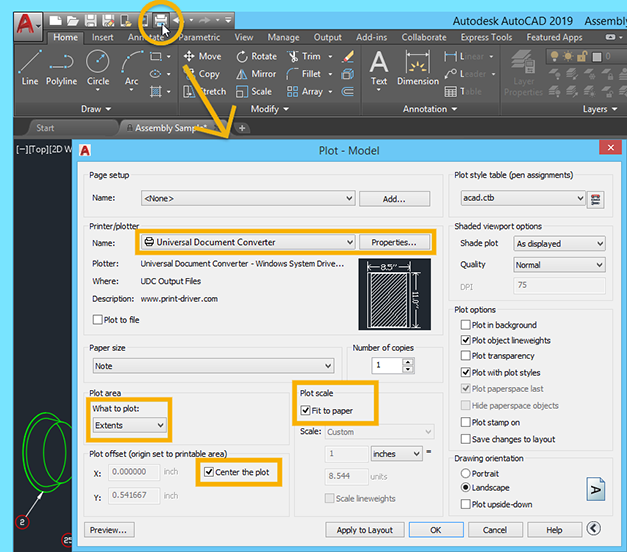
- Adjust the Scale: If necessary, adjust the scale of the projected views to fit the paper space or to emphasize certain parts of the design.
- Add Dimensions and Notes: Use the dimensioning tools to add measurements to your views. You can also add notes and labels to provide additional information about the design.
- Finalize the Drawing: Review your projections for accuracy and completeness. Make any necessary adjustments to ensure that the views accurately represent the 3D model.
By following these steps, you can effectively create detailed and accurate 3-view orthographic projections in AutoCAD, essential for design documentation, analysis, and communication.

Utilizing Ortho and Polar Tracking for Enhanced Drafting Efficiency
AutoCAD\"s Ortho and Polar Tracking features are essential tools for improving drafting efficiency, ensuring precision, and speeding up the design process. These features help in drawing straight lines exactly horizontal or vertical (Ortho Mode) and at specified angles (Polar Tracking), respectively. This section explains how to effectively use these features for enhanced drafting efficiency.
- Activating Ortho Mode: Toggle Ortho Mode by pressing F8. This mode restricts cursor movement to horizontal and vertical directions, ideal for drawing straight lines without manually aligning them.
- Using Polar Tracking: Polar Tracking can be enabled by pressing F10. It allows drawing lines at specific angles predefined by the user, aiding in maintaining consistency across angled elements.
- Setting Polar Tracking Angles: Customize Polar Tracking angles through the drafting settings. You can set standard angles or add custom angles based on project requirements to guide your cursor movement.
- Combining Ortho and Polar Tracking: Use both features in tandem to switch between orthogonal and angled drawing seamlessly, enhancing drafting speed and accuracy.
- Snapping to Angles: With Polar Tracking activated, your cursor will snap to the predefined angles, reducing the need for manual input and ensuring precision in your designs.
- Adjusting Tracking Settings: Adjust the granularity of the tracking angles and the behavior of Ortho Mode in the AutoCAD settings to fit your drafting style and project needs.
By mastering Ortho and Polar Tracking, drafters can significantly reduce drafting time and increase accuracy, making these tools indispensable for any efficient CAD workflow.
AutoCAD Orthographic Projection Example 1 - Multi View Drawing
Embark on a mesmerizing journey of creativity as you explore the world of drawing. Unleash your imagination and learn new techniques that will take your artwork to new heights in this captivating video!
Orthographic Projection in AutoCAD Engineering Graphics - Engineering Drawing in AutoCAD Mech20 Tech
Step into the world of precision and innovation with AutoCAD. Discover how this powerful software can revolutionize your design process and bring your ideas to life with unparalleled precision and efficiency in this must-watch video!
Advanced Tools and Techniques in Orthographic Drawing
Orthographic drawing in AutoCAD is not just about creating basic views; advanced tools and techniques can significantly enhance the detail, efficiency, and functionality of your drawings. This section explores some of these advanced features that can take your orthographic drawings to the next level.
- Dynamic Blocks: Use dynamic blocks to create configurable components in your drawings. This allows for the rapid adjustment of size, shape, and features without needing to redraw the block.
- Parametric Constraints: Apply parametric constraints to maintain relationships between drawing geometry. This is particularly useful for maintaining the consistency of your designs as changes are made.
- Layer States Manager: Utilize the Layer States Manager to save and restore different layer configurations. This can simplify working with complex drawings by showing or hiding relevant information.
- Data Extraction: Use data extraction tools to pull information from your drawings for use in tables or reports. This can help in creating bills of materials, schedules, and other documentation.
- 3D Visualization Techniques: Though primarily 2D, understanding how to present orthographic drawings with basic 3D visualizations can help in communicating more complex designs.
- Custom Scripts and Automation: Automate repetitive tasks by writing custom scripts or using AutoCAD\"s Action Recorder. This can significantly speed up the drawing process for complex projects.
- Sheet Sets: Manage multiple drawings more efficiently using sheet sets. This feature allows for organizing, publishing, and archiving your drawings as a cohesive project.
Embracing these advanced tools and techniques in AutoCAD can enhance your productivity, improve the quality of your orthographic drawings, and enable more sophisticated design workflows.
READ MORE:
Orthographic Projections: Standards and Symbols
Orthographic projections are a critical aspect of technical drawing, providing a standardized way to represent three-dimensional objects in two dimensions. Understanding the standards and symbols associated with orthographic projection is essential for clear and accurate communication in engineering, architecture, and design. This section covers key standards and symbols used in orthographic drawing within AutoCAD.
- Projection Standards: There are two main types of projection standards used globally—ISO (International Organization for Standardization) and ASME (American Society of Mechanical Engineers). ISO uses the first-angle projection method, while ASME prefers the third-angle projection. Choosing the correct standard depends on your geographical location or project requirements.
- View Labels: Orthographic drawings typically include labels such as \"TOP VIEW,\" \"FRONT VIEW,\" and \"SIDE VIEW\" to indicate the perspective of each projection. Proper labeling is crucial for the interpretation of the drawing.
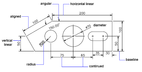
- Dimensioning Standards: Both ISO and ASME have specific guidelines for dimensioning practices to ensure consistency and clarity in measurements. This includes placement, font size, and line types used for dimensioning.
- Line Types and Symbols: Various line types and symbols are used to represent different features in orthographic drawings. These include continuous lines for visible edges, dashed lines for hidden edges, and chain lines for center lines or paths of motion.
- Section Views: Section views are denoted by cutting planes, indicated by a line with arrows at both ends, labeled with letters. A corresponding section view is then provided, labeled with the same letters to show details not visible from the exterior.
- Standard Symbols: Symbols are used to represent common features such as surface finish, welding requirements, and tolerances. Familiarity with these symbols is essential for accurately interpreting and creating drawings.
Adhering to these standards and utilizing the correct symbols in orthographic projections ensures that your drawings are professional, accurate, and universally understood.
Mastering orthographic drawing in AutoCAD unlocks endless possibilities for precision, creativity, and efficiency in design. Embrace these techniques to elevate your drafting skills and bring your engineering and architectural visions to life.