Topic how do you scale a drawing in autocad: Mastering the art of scaling drawings in AutoCAD enhances precision and efficiency. Discover essential techniques and tips to scale like a pro, ensuring your projects are executed flawlessly.
Table of Content
- How do you scale a drawing in AutoCAD?
- Understanding Scale in AutoCAD
- Starting with the SCALE Command
- Selecting Objects to Scale
- Choosing a Base Point for Scaling
- Specifying the Scale Factor
- Scaling with Reference
- YOUTUBE: AutoCAD Scale to Specific Length
- Using Viewports to Scale in Paper Space
- Adjusting Scale for Layouts and Viewports
- Common Scaling Mistakes and How to Avoid Them
- Scaling Blocks and Attributes
- Tips for Scaling Images and PDFs
- Setting the Correct DIMSCALE for Scaled Dimensions
- Practical Examples of Scaling in AutoCAD Projects
How do you scale a drawing in AutoCAD?
To scale a drawing in AutoCAD, you can follow these steps:
- Select the object or line whose length you know in the drawing that is not at a 1:1 scale.
- Start the scaling command by typing SC or SCALE in the command line and pressing Enter.
- Specify a base point by clicking on a point in the drawing or typing coordinates.
- Specify a scale factor by entering a value or selecting a reference length.
- Press Enter to complete the scaling operation.
If you want to change the scale of a drawing view:
- Move the cursor over the drawing view you want to edit. The drawing view border will appear.
- Click on an empty area inside the drawing view.
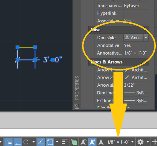
- From the context menu, select \"Properties\" to open the Properties palette.
- In the Properties palette, scroll down to find the \"Scale\" property.
- Enter a new scale value or select a scale from the drop-down menu.
- Press Enter or click outside the Properties palette to apply the scale changes.
If you have created a viewport in Paperspace:
- Click on the viewport you created in Paperspace to highlight it.
- Look at the very top of the screen, where it should say \"Viewport\" in the selection box.
- Now, go to the Ribbon and click on the \"View\" tab.
- In the \"Scale\" panel, you can select a preset scale from the drop-down menu or enter a custom scale value.
READ MORE:
Understanding Scale in AutoCAD
Scaling in AutoCAD is a fundamental skill that allows you to adjust the size of your drawing objects without altering their proportions. It\"s crucial for ensuring that your design fits on the intended plot or model size and that details are accurately represented at different scales. Understanding how scale works in AutoCAD can help you create more precise and readable drawings.
- Scale Factor: This is the ratio of the plotted size to the actual size. For instance, a scale factor of 1:100 means that one unit in the drawing equals 100 units in the real world.
- Units and Precision: Before scaling, ensure your drawing\"s units match the intended output. Accuracy in unit setup is crucial for scaling success.
- Types of Scaling: AutoCAD allows for two primary scaling methods: scaling objects within the model space to adjust their size directly and scaling viewports in the layout to represent the drawing at different scales.
- Applying Scale Commands: The SCALE command is used to scale objects in the model space. You can specify a base point and then either enter a scale factor or select two points to define the scale proportionally.
- Viewport Scaling: In layout views, viewports can be scaled to display the model space drawing at different scales. This is essential for creating detailed sections or overview plans within the same drawing.
Grasping these concepts ensures that you can effectively scale drawings, making them more useful and adaptable to various project needs. It\"s a critical component of the drafting process in AutoCAD, affecting the readability and practicality of your final designs.
Starting with the SCALE Command
The SCALE command in AutoCAD is a powerful tool that allows you to change the size of your objects while maintaining their proportions. Understanding how to use this command effectively is essential for any AutoCAD user looking to adjust their drawings accurately.
- Select the SCALE Command: You can initiate the SCALE command either by typing \"SCALE\" into the command line or accessing it from the Modify panel on the ribbon.
- Choose Your Objects: After initiating the command, select the objects you wish to scale. You can select multiple objects by clicking on them one by one or by using a selection window.
- Specify the Base Point: Once your objects are selected, you will need to choose a base point. This point acts as the anchor for the scaling operation, meaning your objects will scale relative to this point.
- Enter a Scale Factor: After choosing a base point, you can specify your scale factor. This can be a numerical value representing the proportion you wish to scale your objects by. For example, entering a value of 2 will double the size of your objects, while 0.5 will halve them.
- Using Reference for Scaling: Instead of specifying a scale factor, you can choose two points to define the scale factor based on the distance between them. This method is particularly useful when you need to match the scale of an object to a specific dimension within your drawing.
Mastering the SCALE command requires practice, but once familiar, it significantly enhances your ability to manipulate drawing sizes with precision. It\"s a critical skill for adapting drawings to various project requirements and ensuring your designs are accurately represented at any scale.
Selecting Objects to Scale
Selecting the correct objects to scale is a fundamental step in the scaling process in AutoCAD. It ensures that you only modify the elements necessary for your design adjustments. Here\"s how to accurately select objects for scaling:
- Use the Mouse: Click on an object to select it. For multiple objects, click each one while holding the Shift key. This method is straightforward and allows for precise selection.
- Selection Window: Click and drag to create a selection window. Objects completely within the window will be selected. This is useful for selecting groups of objects.
- Crossing Window: Click and drag in the opposite direction to create a crossing window. Objects that are either completely within or touching the boundary of the window will be selected. This method is helpful for selecting objects in dense areas.
- Using Filters: AutoCAD allows you to use filters to select objects based on their properties (e.g., layer, color, type). This can be accessed through the Quick Select feature, enabling you to select objects with specific characteristics.
- Select All: If you need to scale all objects in the drawing, you can use the \"Select All\" command by typing \"ALL\" when prompted to select objects. Be cautious with this approach, as it will include every object in your drawing.
Effectively selecting objects to scale is crucial for efficient workflow and precision in AutoCAD. By mastering these selection techniques, you can ensure that your scaling operations are accurate and only affect the intended parts of your drawing.

Choosing a Base Point for Scaling
Choosing the correct base point when scaling objects in AutoCAD is critical for ensuring your scaled elements are positioned accurately. The base point serves as the anchor from which your objects will be scaled, affecting their final placement and orientation. Here are steps and considerations for selecting an appropriate base point:
- Understand Your Design Needs: Before selecting a base point, consider how the scaled object needs to relate to other elements in your drawing. Your base point choice should support these relational needs.
- Choosing a Specific Point: You can select a specific point on an object as the base point, such as a corner, endpoint, or midpoint. This is useful when you need to scale an object in relation to a particular location.
- Using Object Snaps: Object snaps (OSNAP) can help you select precise points as your base point, ensuring accuracy. For example, you might use the endpoint snap to select the corner of a rectangle as your base point.
- Consider the Center of an Object: For objects that need to be scaled uniformly in all directions, choosing the geometric center as the base point can be effective. This maintains the object\"s placement while altering its size.
- External Reference Points: Sometimes, it may be beneficial to choose a base point that is not part of the object being scaled, such as another object\"s endpoint or a specific location in your drawing. This approach is useful when scaling multiple objects in relation to a single point.
Choosing the right base point is a decision that can significantly impact the effectiveness and accuracy of your scaling operation. It requires a good understanding of both your design goals and the scaling tools available in AutoCAD. With practice, selecting the optimal base point will become an intuitive part of your scaling workflow.
_HOOK_
Specifying the Scale Factor
Specifying the scale factor is a crucial step in scaling objects in AutoCAD, determining how much the selected objects will increase or decrease in size. Here\"s how to accurately specify the scale factor for your needs:
- Understand Scale Factor Basics: The scale factor represents the ratio of the new size to the original size. A scale factor greater than 1 enlarges the object, while a scale factor less than 1 reduces its size.
- Direct Input: After selecting your objects and base point, you can directly input a numerical scale factor. For instance, typing \"2\" doubles the size of the objects, whereas \"0.5\" halves their size.
- Reference Scaling: Instead of entering a scale factor directly, you can use the \"Reference\" option. Select two points to define the current dimension and then specify the desired length. AutoCAD will automatically calculate and apply the appropriate scale factor.
- Scaling with Units: If you are working with different units (e.g., scaling a drawing from meters to millimeters), calculate the scale factor accordingly. For example, to scale up from meters to millimeters, you would use a scale factor of 1000.
- Repetitive Scaling: For operations requiring repetitive scaling (e.g., creating a series of objects that decrease in size), it can be useful to note down or use a calculator to determine consistent scale factors that meet your design requirements.
Correctly specifying the scale factor ensures that your objects are scaled accurately, maintaining the intended proportions and relationships within your drawing. This step is essential for achieving precision in your AutoCAD projects.

Scaling with Reference
Scaling with reference in AutoCAD allows you to adjust the size of an object based on a specific measurement or reference point, ensuring accuracy and proportionality. This method is particularly useful when you need to match the scale of an object to a predefined dimension or another object. Here\"s how to scale with reference effectively:
- Initiate the SCALE Command: Start by selecting the SCALE command, either through typing it into the command line or selecting it from the toolbar.
- Select Objects to Scale: Choose the objects you wish to scale. You can select individual objects or use a selection window to choose multiple objects at once.
- Specify the Base Point: Choose a base point. This point will remain fixed, and the selected objects will scale in relation to this point.
- Choose the Reference Option: When prompted to specify the scale factor, type \"R\" to select the Reference option. This allows you to define the scaling operation based on a reference length.
- Specify the Original Reference Length: Select two points to define the original length that you want to change. This could be the distance between two points on an object or any specific measurement on your drawing.
- Enter the New Length: After specifying the original reference length, enter the new desired length. AutoCAD will calculate the necessary scale factor to transform the original length into the new length.
Using the scaling with reference technique ensures that your scaled objects precisely match specific dimensions or align perfectly with other elements in your design. It\"s an invaluable tool for detailed and accurate drafting work in AutoCAD.
AutoCAD Scale to Specific Length
\"Discover the power of AutoCAD and unlock your creativity in the world of design! Watch our video to learn how this industry-leading software can revolutionize your drafting and modeling skills.\"
AutoCAD 6 - How to Scale a Drawing in AutoCAD
\"Master the art of precision with the use of scale in our video tutorial. Learn how to accurately measure and represent objects in their true proportions, providing a professional touch to your architectural or engineering projects.\"
Using Viewports to Scale in Paper Space
Viewports in AutoCAD\"s Paper Space allow you to display different parts of your model at various scales on a single layout. This feature is particularly useful for creating detailed plans and sections alongside overall site layouts. Here\"s how to use viewports to scale effectively in Paper Space:
- Create a New Viewport: In the layout tab, use the \"MVIEW\" command to create a new viewport. You can draw the viewport boundary manually or use predefined shapes.
- Select the Viewport: Click inside the viewport to select it. Once selected, the viewport\"s border will highlight, indicating it is active.
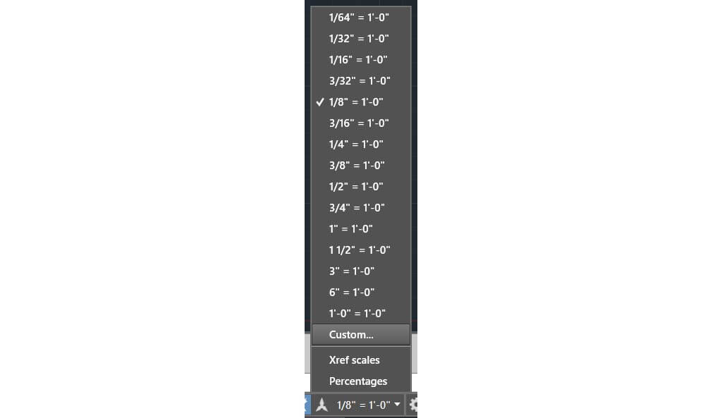
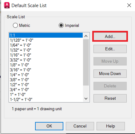
- Set the Scale: With the viewport selected, look for the scale list in the status bar at the bottom of the screen. Choose a scale from this list that best fits the view you need. The list includes common architectural and engineering scales.
- Lock the Viewport: To prevent accidental scaling or panning within the viewport, it\"s a good practice to lock it. Right-click on the viewport\"s border, select \"Properties,\" and then toggle the \"Display Locked\" property to \"Yes.\"
- Adjusting Viewport Properties: You can further customize the viewport by adjusting its properties, such as layer visibility and visual style, to ensure that the scaled view communicates the necessary information effectively.
Using viewports to scale in Paper Space enables precise control over how your design is presented, allowing for multiple perspectives and scales to be displayed cohesively on a single sheet. This method enhances clarity and communication in your AutoCAD drawings.

Adjusting Scale for Layouts and Viewports
Adjusting the scale for layouts and viewports in AutoCAD allows for precise control over how your designs are displayed on paper. This process is crucial for ensuring that detailed drawings and plans are clearly visible and accurately represent the real-world size of objects. Follow these steps to adjust scale effectively:
- Access Layout Settings: Navigate to the layout tab that you wish to adjust. Each layout tab represents a different page setup for printing or exporting your drawing.
- Create or Modify Viewports: Use the \"MVIEW\" command to create new viewports or select existing ones. You can have multiple viewports in a single layout, each with a different scale.
- Choose a Scale for Each Viewport: After selecting a viewport, you can set its scale from the scale list in the viewport\"s properties or from the drop-down menu in the status bar. Ensure the scale accurately represents the intended real-world dimensions.
- Lock the Viewport Scale: Once the desired scale is set, lock the viewport to prevent unintended changes. This can be done by right-clicking the viewport border, selecting \"Properties,\" and enabling \"Display Locked.\"
- Adjust Viewport Layers and Styles: Fine-tune which layers are visible and the visual styles within each viewport. This step ensures that each viewport communicates the intended aspects of your design.
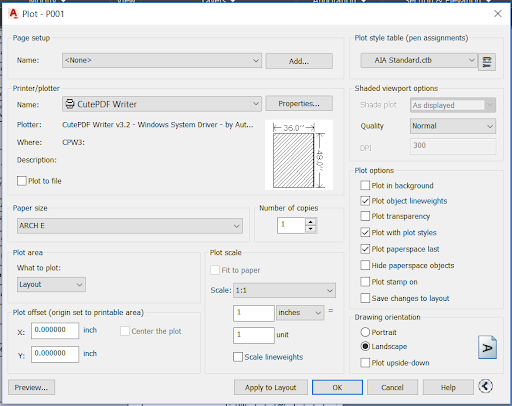
- Update Layout Properties: Finally, adjust the layout\"s properties, such as paper size, orientation, and plot scale, to ensure that the viewports and the overall layout are aligned with your printing or presentation requirements.
By carefully adjusting the scale for layouts and viewports, you can ensure that your AutoCAD drawings are presented professionally, with clear, detailed, and accurately scaled representations of your designs.
Common Scaling Mistakes and How to Avoid Them
Scaling in AutoCAD is a crucial process that, if done incorrectly, can lead to significant errors in your drawings. Understanding common scaling mistakes can help you avoid them and ensure your drawings are accurate and professional. Here are some common mistakes and tips on how to avoid them:
- Incorrect Scale Factor: Using the wrong scale factor is a common mistake. Always double-check your scale factor before applying it, ensuring it matches the intended real-world dimensions of your project.
- Not Locking Viewports: Failing to lock viewports can lead to accidental changes in scale. Always lock your viewports once the correct scale is set to prevent unintended alterations.
- Mixing Units: Mixing measurement units (e.g., inches and millimeters) can lead to scaling errors. Ensure consistency in units throughout your drawing process.
- Ignoring Drawing Units: Not setting or ignoring the drawing units at the beginning of your project can result in incorrect scales. Set your drawing units according to your project needs before starting to scale.
- Scaling Text and Dimensions Incorrectly: Text and dimensions should often be readable and not scaled along with the model. Use the annotation scale features to keep text and dimensions consistent and legible across different scales.
- Forgetting to Scale Blocks or Xrefs: Blocks and external references (Xrefs) must be scaled appropriately to match the rest of your drawing. Pay special attention to these elements to ensure they fit seamlessly into your scaled drawing.
Avoiding these common mistakes requires attention to detail and a thorough understanding of AutoCAD\"s scaling functions. By being mindful of these pitfalls, you can produce accurately scaled and professional-quality drawings.

_HOOK_
Scaling Blocks and Attributes
Scaling blocks and attributes correctly in AutoCAD ensures that your drawing maintains consistency and accuracy, especially when working with repeated elements or symbols. Here’s a guide to effectively scale blocks and attributes:
- Understand Block Scalability: Blocks can be created to scale automatically upon insertion or to remain at a fixed scale. Decide which option suits your project needs when creating or inserting blocks.
- Use the SCALE Command on Blocks: To manually scale a block, select it and use the SCALE command just as you would with any other object. Remember to select a base point that makes sense for how the block should scale within your drawing.
- Adjusting Block Attribute Scaling: If your block contains attributes (text or dimensions), ensure that these attributes are set to scale properly with the block. This may involve setting the attribute properties to ensure they maintain readability and accuracy at different scales.
- Global Scale Factor for Blocks: You can set a global scale factor that affects all blocks upon insertion. This is particularly useful when working with blocks from external libraries that may not be scaled for your current project settings.
- Scaling Blocks in Block Editor: For more control over how individual components of a block scale, use the Block Editor. This allows you to adjust the scaling of components individually, ensuring that the block behaves as intended when scaled.
- Uniform Scale Option: When creating or editing blocks, consider using the \"Uniform Scale\" option to ensure that the block scales equally in all directions, maintaining its proportions.
Properly scaling blocks and attributes in AutoCAD is essential for creating coherent and scalable drawings. By following these guidelines, you can ensure that your blocks and attributes contribute positively to your project, maintaining consistency and accuracy across different scales.
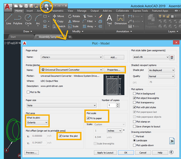
Tips for Scaling Images and PDFs
Scaling images and PDFs in AutoCAD requires precision to ensure that these external references fit accurately within your design. Here are some tips to scale images and PDFs effectively:
- Check the Reference Scale: Before scaling an image or PDF, determine if there\"s a known scale (e.g., 1:100) used in the document. This information is crucial for accurate scaling.
- Use the ALIGN Command: For images and PDFs, the ALIGN command can be more effective than SCALE. It allows you to match the image/PDF to specific points in your drawing, automatically scaling it to fit.
- Set Insertion Points: When inserting an image or PDF, carefully select the insertion point and scale factor. If the scale is known, input it directly; if not, adjust it manually until it matches your drawing’s scale.
- Calibrate the Scale: If scaling manually, use a known dimension within the image or PDF to calibrate the scale. Measure a known length, then scale the image or PDF until the measurements match.
- Lock the Scale of External References: Once your image or PDF is correctly scaled, use the properties palette to lock the scale, preventing accidental resizing during further editing.
- Maintain Aspect Ratio: Ensure that the aspect ratio is locked when scaling images to prevent distortion. This is typically done automatically but is worth verifying.
By following these tips, you can ensure that images and PDFs inserted into your AutoCAD drawings are scaled accurately, maintaining the integrity of your design and ensuring that all elements are proportionally correct.
Setting the Correct DIMSCALE for Scaled Dimensions
Setting the correct DIMSCALE (Dimension Scale) is crucial for creating readable and accurate dimensions in scaled drawings in AutoCAD. It affects the size of dimension text, arrows, and other dimension elements. Follow these steps to set the correct DIMSCALE for your project:
- Understand the Purpose of DIMSCALE: DIMSCALE controls the overall scale factor applied to dimensions. A correct DIMSCALE ensures that dimensions appear at a consistent, readable size, regardless of the drawing scale.
- Determine the Drawing Scale: Before setting the DIMSCALE, know the scale at which the drawing will be printed or viewed. This scale directly influences the DIMSCALE setting.
- Setting DIMSCALE: Access the DIMSTYLE manager by typing \"DIMSTYLE\" into the command line. Here, you can adjust the DIMSCALE to match your intended drawing scale. For example, if your drawing is at a 1:100 scale, setting DIMSCALE to 100 may be appropriate.
- Test Dimension Appearance: After setting DIMSCALE, place some test dimensions in your drawing to verify their readability and appearance. Adjust the DIMSCALE as needed based on these tests.
- Use Annotative Dimensions for Flexibility: Consider using annotative dimensions, which automatically adjust their size based on the scale of the viewport they are viewed in. This can simplify the process of managing dimensions across multiple scales.
- Adjust Individual Dimension Styles: If necessary, you can adjust the scale of individual dimension styles through the Properties palette. This is useful for fine-tuning the appearance of dimensions in specific parts of your drawing.
Correctly setting the DIMSCALE is essential for ensuring that dimensions are clear and proportional in your scaled drawings. By carefully selecting and testing your DIMSCALE settings, you can enhance the precision and readability of your AutoCAD projects.
READ MORE:
Practical Examples of Scaling in AutoCAD Projects
Scaling in AutoCAD is a versatile tool that can be applied in various ways across different projects. Here are some practical examples showcasing how scaling can be effectively used in AutoCAD projects:
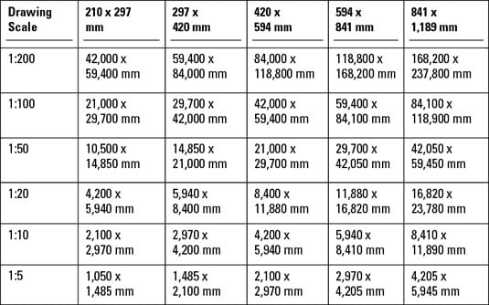
- Architectural Floor Plans: Scaling down detailed architectural plans to fit on standard-sized sheets without losing detail. Using viewports in paper space to display different sections of the plan at various scales.
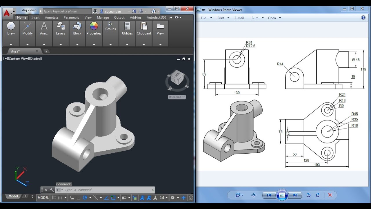
- Engineering Components: Scaling components in mechanical engineering drawings to real-world sizes. This ensures that parts fit together as intended in the physical world.
- Site Plans: Scaling site plans for large projects, such as landscaping or urban planning, to provide an overview while still including detailed sections through viewports at different scales.
- Interior Design Projects: Using scaling to fit furniture and fixtures into floor plans accurately. This helps in visualizing space requirements and clearance areas around objects.
- Map Creation: Scaling geographical data to create maps of varying scales, from detailed local area maps to broader regional or national overviews.
- Creating Scale Models: For projects that involve creating physical models, such as in architecture or product design, scaling drawings to ensure models are accurate representations of the final product.
These examples highlight the importance of mastering scaling techniques in AutoCAD to enhance the accuracy, readability, and overall effectiveness of your drawings. Whether you are working on small-scale components or large architectural projects, understanding how to apply scaling correctly is crucial for success.
Mastering scaling in AutoCAD unlocks a world of precision and efficiency in your designs. Embrace these insights to transform your drawings, ensuring they meet the highest standards of accuracy and professionalism in every project.