Topic how to draw in autocad: Discover the art of drafting in AutoCAD with our comprehensive guide. From basic lines to complex 3D models, we"ll walk you through each step to unleash your creativity and enhance your skills in this powerful software.
Table of Content
- How can I learn AutoCAD step-by-step with video lessons and practice exercises for free?
- Getting Started with AutoCAD
- Understanding AutoCAD Interface and Basic Commands
- Setting Up Your Drawing Environment
- Drawing Basic Shapes and Lines
- Using Coordinates and the Grid System
- Mastering Drawing Tools: Line, Rectangle, Circle, and Polygon
- YOUTUBE: AutoCAD Basic Tutorial for Beginners - Part 1
- Modifying Objects: Move, Copy, Rotate, Scale, and Mirror
- Utilizing Layers, Colors, and Linetypes
- Creating and Managing Blocks
- Dimensioning and Annotation
- Advanced Drawing Techniques: Isometric and 3D Drawings
- Preparing and Exporting Your Drawings
How can I learn AutoCAD step-by-step with video lessons and practice exercises for free?
1. Open your web browser and search for \"free AutoCAD video lessons and practice exercises\" on a search engine such as Google.
2. Scan through the search results and look for a website or online platform that offers step-by-step AutoCAD lessons with video tutorials and practice exercises.
3. Click on the relevant search result that seems to provide comprehensive AutoCAD learning resources.
4. Once you have landed on the website, navigate to the AutoCAD section or look for a beginner\'s guide to AutoCAD.
5. Start watching the video lessons provided on the website. Make sure to follow along with the instructor and pay attention to the explanations.
6. After each video lesson, practice what you have learned by working on the provided exercises or by creating your own drawings in AutoCAD.
7. If the website offers quizzes or assessments, take them to test your understanding of the concepts taught in the video lessons.
8. Repeat steps 5-7 for each video lesson available on the website. It is crucial to practice and reinforce what you have learned.
9. Take advantage of any additional learning resources provided on the website, such as written tutorials, tips and tricks, or forums where you can ask questions or interact with other AutoCAD learners.
10. Dedicate regular time to practicing AutoCAD and continue exploring more advanced topics as your skills and knowledge improve.
READ MORE:
Getting Started with AutoCAD
Welcome to the exciting world of AutoCAD! This section will guide you through the initial steps to get started with AutoCAD, ensuring a smooth and efficient learning journey. Whether you\"re a beginner or looking to refresh your skills, follow these steps to begin your drafting adventure.
- Install AutoCAD: Begin by installing AutoCAD on your computer. Follow the installation prompts and ensure your system meets the software requirements.
- Open AutoCAD: Once installed, launch AutoCAD. You\"ll be greeted with the Start Screen, where you can access recent documents or start a new drawing.
- Explore the User Interface: Familiarize yourself with the AutoCAD workspace. The interface includes the ribbon, command line, status bar, and drawing area. Hover over icons to see their functions.
- Set Up Your Drawing Environment: Before drawing, configure your workspace settings. Set your units, drawing limits, and grid settings to match the scale of your project.
- Practice Basic Commands: Learn basic commands like LINE, RECTANGLE, CIRCLE, and MOVE. These foundational tools are crucial for creating simple drawings.
- Save Your Work: Practice saving your work frequently. Use the QSAVE command or click the save icon. It\"s also a good idea to utilize AutoCAD\"s autosave feature.
- Access Help Resources: If you encounter difficulties, the AutoCAD Help system is an invaluable resource. Press F1 for context-sensitive help or search the online forums and tutorials for advice.
By following these steps, you\"ll be well on your way to mastering AutoCAD. Remember, practice is key to becoming proficient, so don\"t hesitate to experiment with different tools and commands as you learn.

Understanding AutoCAD Interface and Basic Commands
Mastering the AutoCAD interface and its basic commands is crucial for efficiently creating and modifying drawings. This section introduces the essential components of the AutoCAD interface and the foundational commands that every user should know.
- Ribbon: The Ribbon is your main toolbar, housing groups of tools organized under tabs such as Home, Insert, Annotate, View, and Manage. Spend time exploring each tab to understand the available tools.
- Command Line: At the bottom of the screen, the Command Line allows you to input commands, view prompts, and receive feedback from AutoCAD. Familiarize yourself with typing commands and using shortcuts for efficiency.
- Workspaces: AutoCAD offers different workspaces tailored to various tasks, such as drafting, 3D modeling, and layout management. Switch between them to find the setup that best suits your project\"s needs.
- Navigation Tools: Tools like Zoom, Pan, and Orbit help you navigate through your drawings. Practice using these tools to efficiently view different parts of your drawing.
- Properties Panel: The Properties panel displays information about selected objects and allows you to modify their attributes, such as color, layer, and dimensions.
- Layer Control: Managing layers is fundamental in organizing your drawing. Use the Layer Properties Manager to create, modify, and assign objects to layers.
- Basic Drawing Commands: Learn the commands for creating basic shapes (e.g., LINE, CIRCLE, RECTANGLE) and practice using them to develop simple drawings.
- Modification Commands: Familiarize yourself with modification commands such as MOVE, COPY, ROTATE, and SCALE, which are essential for editing your drawings.
- Object Snaps: Object Snaps (Osnap) are a powerful feature for achieving precision in your drawings. Learn to use snaps like Endpoint, Midpoint, and Intersection to accurately position objects.
By understanding and practicing these components and commands, you\"ll build a solid foundation in AutoCAD. Remember, practice and exploration are key to becoming proficient in using the software.

Setting Up Your Drawing Environment
Setting up your drawing environment in AutoCAD is a crucial step that ensures efficiency and accuracy in your work. This section guides you through configuring your workspace to suit your project requirements, including units, drawing area, and grid settings.
- Choose the Right Units: Start by setting the drawing units to match the dimension you will work with, such as millimeters, inches, or feet. Use the UNITS command to open the Drawing Units dialog box and make your selection.
- Adjust the Drawing Limits: Set your drawing limits to define the working area. Use the LIMITS command, enter the lower left corner (usually 0,0), and specify the upper right corner based on the size of your project.
- Configure the Grid and Snap: The grid can help guide your drawing by providing a reference, while snap settings ensure precision by \"snapping\" your cursor to exact points. Use the GRID and SNAP commands to adjust these settings.
- Set Up Layers: Organize your drawing by creating layers for different types of information, such as dimensions, text, and construction geometry. Use the LAYER command to manage your layers, setting different colors, linetypes, and other properties for each layer.
- Customize the Interface: Tailor the AutoCAD interface to your preferences by customizing the ribbon, toolbars, and palettes. Right-click on the workspace name in the status bar to switch between workspaces or customize your own.
- Save Your Workspace: After setting up your environment, save these settings as a workspace so you can easily switch back to it for future projects. This saves time and ensures consistency across your work.
By carefully setting up your drawing environment before you begin your project, you can streamline your workflow and ensure that your drawings are accurate and conform to the required standards.
Drawing Basic Shapes and Lines
Learning to draw basic shapes and lines is the foundation of working with AutoCAD. This section will guide you through the process of using simple commands to create your first geometrical figures and lines, which are essential for any AutoCAD drawing.
- Starting with Lines: Use the LINE command to draw straight lines. Enter \"LINE\" into the command prompt, then click or type the start point and the end point of your line.
- Drawing Rectangles: The RECTANGLE command allows you to create rectangles quickly. Specify the first corner point and the diagonal corner point to draw it.
- Creating Circles: With the CIRCLE command, you can draw a circle by specifying the center point and radius. There are options to define circles by diameter, two points, or three points as well.
- Making Polygons: Use the POLYGON command to draw regular polygons. You\"ll need to specify the number of sides and the radius of the circumscribed circle.
- Utilizing Arcs: The ARC command offers several ways to draw arcs, including specifying three points, a start point with an end point and radius, or a start point with a center and end point.
- Applying Polylines: POLYLINE creates a sequence of connected lines and arcs, allowing for more complex and flexible shapes. Enter \"PLINE\" and then the series of points you want to connect.
These basic commands are your tools for creating the fundamental components of any drawing in AutoCAD. Practice using them to become comfortable with producing a wide range of shapes and designs.
_HOOK_
Using Coordinates and the Grid System
Understanding how to use coordinates and the grid system is vital for precise drawing in AutoCAD. This section covers the basics of navigating and drawing using the Cartesian coordinate system and how the grid system can assist in your design process.
- Understanding Coordinates: AutoCAD uses a Cartesian coordinate system with X (horizontal), Y (vertical), and Z (depth) axes. You can specify points in your drawing using these coordinates for exact placement.
- Entering Absolute Coordinates: To draw using absolute coordinates, simply type the X and Y values separated by a comma (e.g., 4,5) after selecting a drawing command. This places your point at that exact location in the drawing space.
- Using Relative Coordinates: Relative coordinates are based on the last point entered. Type @ followed by the X and Y values (e.g., @3,2) to place a point relative to the previous point.
- Polar Coordinates: Polar coordinates specify a point based on a distance and an angle from a reference point. Enter a distance followed by the angle in brackets (e.g., 100<30).
- Utilizing the Grid System: The grid system overlays a pattern of lines on the drawing area, helping you visualize the spacing of objects. You can enable or disable the grid, as well as adjust its spacing to suit your project\"s scale.
- Snapping to Grid: Snap mode forces your cursor to adhere to the grid points, enhancing drawing accuracy. This is especially useful for maintaining consistent measurements and alignments.
By mastering the use of coordinates and the grid system, you can enhance both the precision and efficiency of your drawing process in AutoCAD. Practice these skills to improve your spatial understanding and accuracy in creating complex designs.
Mastering Drawing Tools: Line, Rectangle, Circle, and Polygon
Gaining proficiency with AutoCAD\"s basic drawing tools—Line, Rectangle, Circle, and Polygon—is essential for creating precise and sophisticated designs. This section will guide you through the steps to effectively use these tools in your projects.
- Line Tool: The Line tool is fundamental for drawing straight segments. Activate it by typing \"LINE\" or selecting it from the Ribbon. Click to set the start point, then click again to define the end point. Press \"Enter\" to complete the line.
- Rectangle Tool: To draw rectangles, use the \"RECTANGLE\" command. Specify the first corner point, then drag or enter dimensions to define the opposite corner. Explore options like fillet, chamfer, and rotation during creation for enhanced shapes.
- Circle Tool: The Circle tool creates perfect circles with various methods. Typing \"CIRCLE\" allows you to specify the center and then the radius or diameter. You can also draw circles by defining two or three points on its circumference.
- Polygon Tool: The Polygon tool is versatile for creating equilateral polygons. Enter \"POLYGON\", specify the number of sides, and then define the center point and radius. You have the option to create inscribed or circumscribed polygons within or around a circle.
Each tool offers unique options and shortcuts to streamline your drawing process. Familiarizing yourself with these tools not only speeds up your work but also opens up new possibilities for your designs. Practice using these tools in various combinations to enhance your proficiency and creativity in AutoCAD.
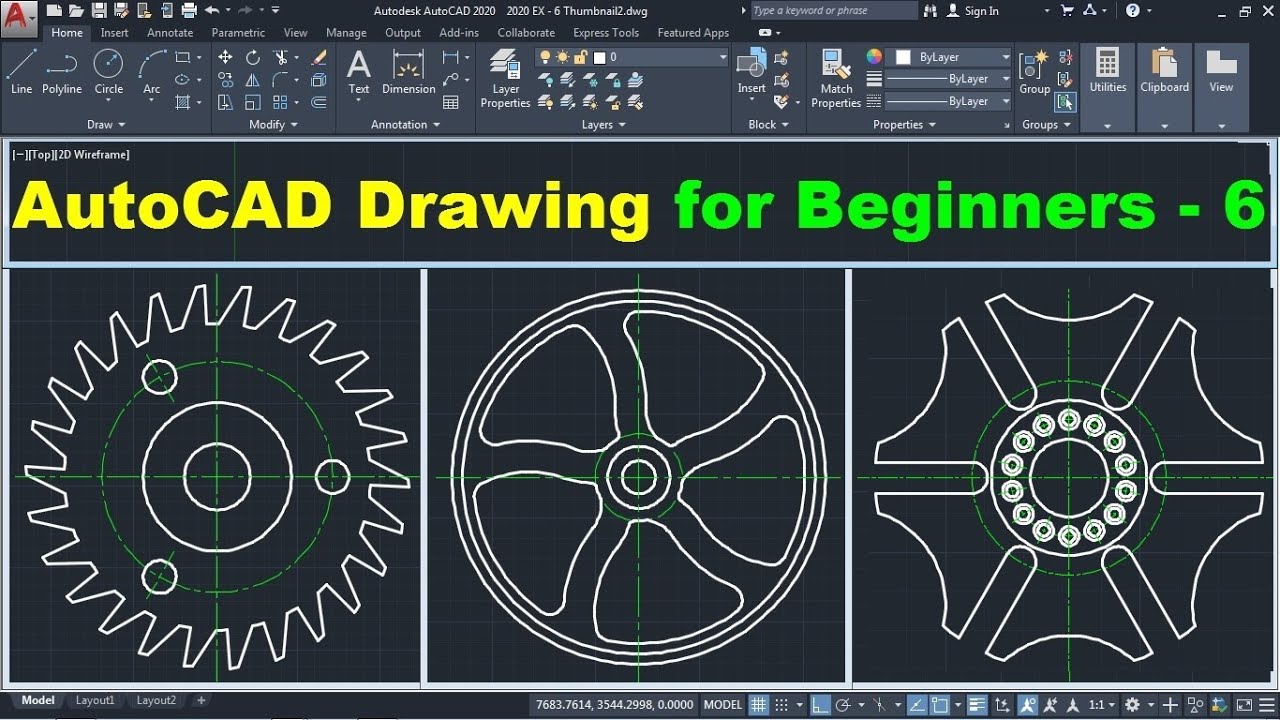
AutoCAD Basic Tutorial for Beginners - Part 1
\"Discover the endless possibilities of AutoCAD in this captivating video! Enhance your design skills as you explore the advanced features and techniques that will take your creations to the next level. Don\'t miss out on this opportunity to become an AutoCAD pro!\"
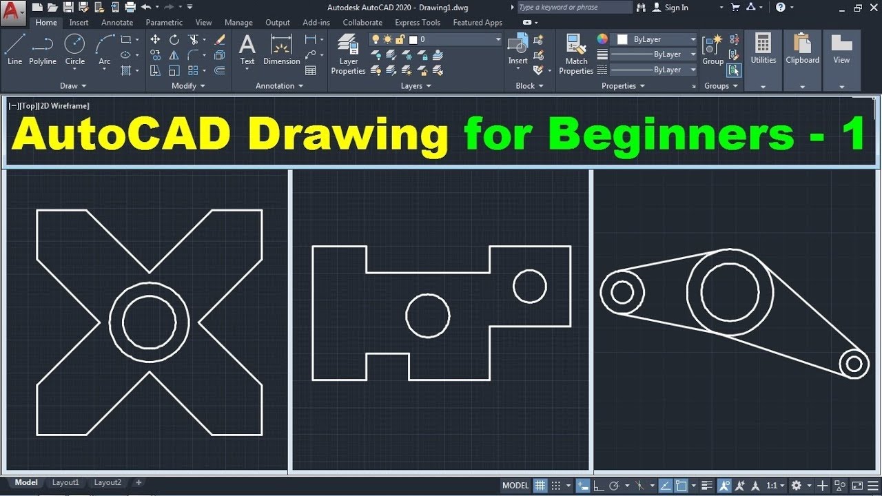
AutoCAD Drawing Tutorial for Beginners - 1
\"Unleash your inner artist and dive into the world of drawing with this inspiring video! Learn the secrets behind every stroke and create stunning masterpieces with ease. Whether you\'re a beginner or a seasoned artist, this video guarantees to ignite your passion for drawing.\"
Modifying Objects: Move, Copy, Rotate, Scale, and Mirror
Gaining proficiency with AutoCAD\"s basic drawing tools—Line, Rectangle, Circle, and Polygon—is essential for creating precise and sophisticated designs. This section will guide you through the steps to effectively use these tools in your projects.
- Line Tool: The Line tool is fundamental for drawing straight segments. Activate it by typing \"LINE\" or selecting it from the Ribbon. Click to set the start point, then click again to define the end point. Press \"Enter\" to complete the line.
- Rectangle Tool: To draw rectangles, use the \"RECTANGLE\" command. Specify the first corner point, then drag or enter dimensions to define the opposite corner. Explore options like fillet, chamfer, and rotation during creation for enhanced shapes.
- Circle Tool: The Circle tool creates perfect circles with various methods. Typing \"CIRCLE\" allows you to specify the center and then the radius or diameter. You can also draw circles by defining two or three points on its circumference.
- Polygon Tool: The Polygon tool is versatile for creating equilateral polygons. Enter \"POLYGON\", specify the number of sides, and then define the center point and radius. You have the option to create inscribed or circumscribed polygons within or around a circle.
Each tool offers unique options and shortcuts to streamline your drawing process. Familiarizing yourself with these tools not only speeds up your work but also opens up new possibilities for your designs. Practice using these tools in various combinations to enhance your proficiency and creativity in AutoCAD.
Utilizing Layers, Colors, and Linetypes
Layers, colors, and linetypes are fundamental tools in AutoCAD that help organize, visualize, and distinguish different parts of your drawing effectively. Mastering their use can significantly enhance the clarity and professionalism of your designs.
Creating and Managing Layers
Layers in AutoCAD are used to separate different elements of your drawings, making it easier to edit and view specific parts of your project. To create a new layer:
- Open the Layer Properties Manager by typing \"LAYER\" in the command line or by clicking on the Layer Properties icon in the Layers panel.
- Click on the New Layer icon, enter a name for your new layer, and press Enter.
- Adjust the properties of your layer, such as color, linetype, and transparency, as needed.
- Make sure to set your new layer as current to start drawing on it.
Organize your layers by naming them according to the elements they represent, such as walls, electrical, plumbing, etc., for easier management and visibility control.
Assigning Colors and Linetypes
Colors and linetypes are essential for differentiating the elements of your drawing. To assign colors and linetypes:
- Select the object(s) you wish to modify.
- Open the Properties panel by typing \"PROPERTIES\" or using the shortcut CTRL+1.
- Under the Color or Linetype dropdown, choose your desired option. AutoCAD provides a wide range of colors and linetypes to suit various drafting standards and preferences.
Use colors and linetypes consistently throughout your drawing to maintain clarity and coherence.
Utilizing Layers for Effective Drawing Management
Effectively utilizing layers involves more than just creating them; it involves strategic planning and organization. Here are some tips for using layers efficiently:
- Always draw new elements on the appropriate layer to maintain organization.
- Use the Layer Off, Freeze, or Lock features to simplify the viewing and editing of complex drawings.
- Utilize layer states to save and restore layer configurations for different phases of your project or for presenting your work.
Benefits of Using Layers, Colors, and Linetypes
Implementing a structured approach to using layers, colors, and linetypes offers several benefits:
- Improved Organization: Helps in managing complex drawings by segregating different elements into layers.
- Enhanced Readability: Colors and linetypes make it easier to distinguish between different types of information, improving the drawing’s overall readability.
- Efficient Editing and Revision: With well-organized layers, making changes and revisions becomes more straightforward, saving time and reducing errors.
By mastering the use of layers, colors, and linetypes, you can enhance the quality and professionalism of your AutoCAD drawings, making them easier to understand and more effective as communication tools.

Creating and Managing Blocks
Blocks in AutoCAD are a powerful feature that allows you to create reusable drawing components. They help in reducing file size, ensuring consistency, and saving time by eliminating the need to redraw repetitive elements. This section will guide you through the process of creating and managing blocks in AutoCAD.
Creating a Block
- Select the objects you want to include in your block. You can do this by clicking on each object while holding down the Shift key, or by using a selection window.
- Type \"BLOCK\" in the command line and press Enter, or access the Block Definition dialog box by clicking on Create Block from the Insert tab.
- In the Block Definition dialog box, enter a name for your block in the Name field.
- Choose a base point for your block. This point will be used as a reference when you insert the block into your drawings.
- Specify the objects to be included in the block by selecting them in the drawing area, if you haven’t already.
- Decide whether you want to retain, convert to block, or delete the original objects.
- Click OK to create your block.
Inserting Blocks
To insert a block into your drawing:
- Type \"INSERT\" in the command line or click on Insert Block from the Insert tab.
- Select the block you wish to insert from the list of available blocks.
- Specify the insertion point, scale, and rotation angle in the drawing area.
- Press Enter or click to place the block.
Managing Blocks
AutoCAD provides several tools for managing blocks within your drawings:
- Block Editor: You can modify existing blocks by using the Block Editor. Simply type \"BEDIT\" in the command line and select the block you wish to edit.
- Purge: To remove unused blocks from your drawing, use the \"PURGE\" command. This helps in reducing file size and keeping your drawing clean.
- Redefine Blocks: If you need to update a block throughout your drawing, you can redefine it. Simply make changes to the block definition and all instances of the block in the drawing will be updated.
Benefits of Using Blocks
- Efficiency: Blocks save time by allowing you to reuse and edit complex components without redrawing them.
- Consistency: Using blocks ensures that repetitive elements in your drawings are consistent in size, shape, and design.
- Organization: Blocks can help in organizing your drawing files, making them easier to navigate and manage.
By effectively creating and managing blocks, you can streamline your drawing process, improve productivity, and enhance the quality of your AutoCAD projects.
_HOOK_
Dimensioning and Annotation
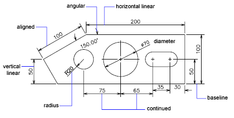
Dimensioning and annotation in AutoCAD are crucial for conveying the exact sizes, shapes, and details of your design to anyone who reads your drawings. Proper use of these tools not only helps in understanding the design but also ensures accurate construction or manufacturing. Here\"s how to effectively use dimensioning and annotation in your drawings.
Adding Dimensions
- To add linear dimensions, select the \"Linear\" dimension tool from the Annotation tab. Click on the first and second points of the element you want to dimension, and then place the dimension line.
- For radial and diametrical dimensions, use the \"Radius\" or \"Diameter\" dimension tools, selecting the arc or circle accordingly, and then placing the dimension.
- Angular dimensions can be added by selecting two lines or by specifying the vertex and two points.
- Adjust the dimension style by right-clicking on an existing dimension and selecting \"Dimension Style\". Here, you can customize text size, dimension lines, and arrowheads to fit your drawing\"s standards.
Creating Annotations
Annotations provide additional information about your drawing, such as material specifications or construction notes. To create annotations:
- Select the \"Multiline Text\" tool from the Annotation tab for longer notes or descriptions. Click and drag in the drawing area to define the text box, and then enter your text.
- For single-line text, use the \"Single Line Text\" tool. Specify the insertion point and then type your text.
- Customize your text style by accessing the Text Style dialog from the Annotation tab, where you can choose font, size, and formatting options.
Using Leaders
Leaders point to specific parts of your drawing, directing attention to your annotations or important features. To add a leader:
- Select the \"Leader\" command from the Annotation tab.
- Click to set the start point of the leader and then the point where the leader line will end. Enter your annotation text at the prompt.
- Customize the leader style through the \"Leader Style\" dialog, accessible from the Annotation tab, to match your drawing\"s aesthetic.
Tips for Effective Dimensioning and Annotation
- Keep your dimensions and annotations clear and readable by adjusting text size and line weights appropriately.
- Use layers to separate dimensions and annotations from other drawing elements, making them easier to manage and modify.
- Adhere to industry or project-specific standards for dimensioning and annotation to ensure your drawings communicate effectively with all stakeholders.
By mastering dimensioning and annotation in AutoCAD, you ensure that your drawings convey all necessary information accurately and efficiently, making them invaluable tools for successful project execution.

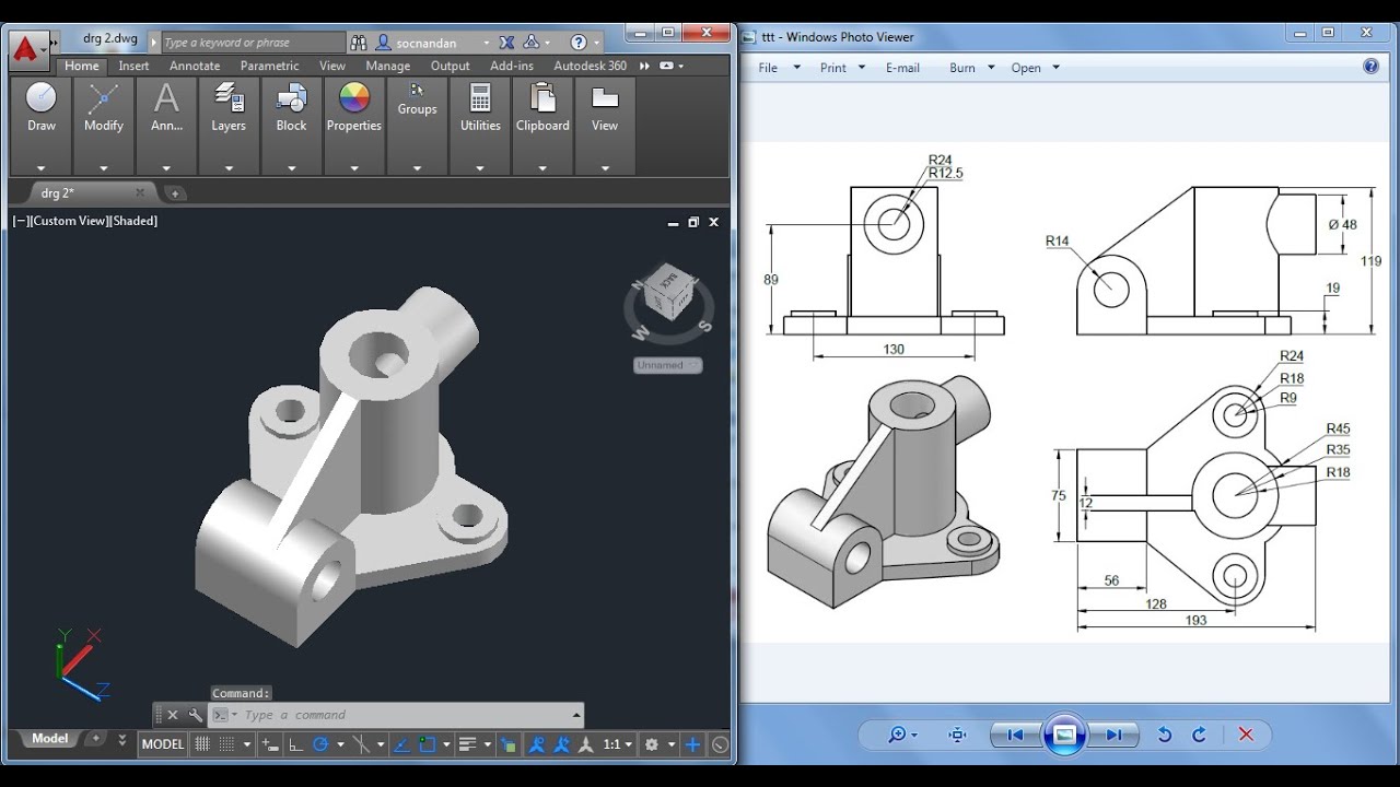
Advanced Drawing Techniques: Isometric and 3D Drawings
Expanding your skill set to include isometric and 3D drawings in AutoCAD can elevate the detail and perspective of your designs, providing a more comprehensive view of your projects. These techniques allow for the visualization of objects in three dimensions, offering a realistic depiction of how a design will appear in the real world.
Creating Isometric Drawings
Isometric drawings represent three-dimensional objects on a two-dimensional plane, typically used for mechanical parts or architectural plans. To create an isometric drawing:
- Switch to isometric drawing mode by clicking on the \"SNAP\" command, typing \"SNAP\" into the command line, or by pressing F9. Then, set the \"Snap type\" to \"Isometric\".
- Use the \"Line\" tool or \"Polyline\" tool to draw your object. You can switch between isoplane views (Top, Right, Left) by pressing the F5 key or by using the \"Isoplane\" command to change the orientation of your lines.
- Draw your object using the isometric grid as a guide to ensure accurate proportions and angles.
Starting with 3D Drawings
3D drawings in AutoCAD enable the creation of solid models, providing a more immersive visualization. To begin with 3D drawing:
- Change your workspace to the 3D modeling environment by selecting \"3D Modeling\" from the workspace switcher located in the top-right corner of the screen.
- Start by using basic 3D shapes from the \"Home\" tab, such as boxes, cylinders, or spheres, to create your model. These shapes can be modified and combined to form complex models.
- Utilize the \"Extrude\", \"Revolve\", \"Sweep\", and \"Loft\" commands to create 3D forms from 2D shapes. These tools can turn 2D profiles into 3D models by extending, rotating, or stretching them along a path.
Editing 3D Models
Once you have your basic 3D model, you can refine it using various editing tools:
- The \"Presspull\" tool allows you to extrude or cut areas of your model simply by clicking on a surface and dragging it.
- Use the \"Move\", \"Rotate\", and \"Scale\" tools to adjust the position, orientation, or size of your model.
- The \"Solid Editing\" tools enable more complex modifications, such as filleting edges, slicing models, and combining or subtracting solid objects.
Tips for Effective Isometric and 3D Drawing
- Regularly use the \"ViewCube\" tool to change your perspective and inspect your model from different angles.
- Apply materials and textures from the \"Visualize\" tab to give your 3D models a more realistic appearance.
- Experiment with different lighting setups and rendering options to enhance the visual impact of your 3D models.
Mastering isometric and 3D drawing techniques in AutoCAD not only enhances the presentation of your designs but also improves your ability to communicate complex details and concepts. With practice, you can create detailed, realistic models that bring your ideas to life.
READ MORE:
Preparing and Exporting Your Drawings
Before sharing or printing your AutoCAD drawings, it\"s essential to prepare and export them correctly to ensure they are presented accurately and professionally. This section will guide you through the process of preparing your drawings for export, choosing the right file format, and finally, exporting them.
- Clean Up Your Drawing
- Begin by removing any unnecessary elements or layers that are not needed in the final output. Use the PURGE command to delete unused blocks, layers, and line types to reduce the file size and simplify your drawing.
- Set the Correct Scale
- Ensure your drawing\"s scale is set correctly for the output. If you\"re printing on paper, adjust the scale so that the drawing fits the paper size or maintains the correct proportions if scaled down.
- Adjust Layouts and Viewports
- Create or modify layouts to present your drawing effectively. Use viewports in paper space to control the scale and portion of your drawing that is displayed on each layout.
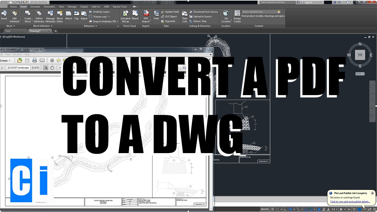
- Choose the Right File Format
- Decide on the appropriate file format for your needs. DWG is the native AutoCAD format, offering the highest fidelity for AutoCAD features. For compatibility with other software, consider exporting to DXF. For sharing with clients or printing, PDF is often the best choice for its wide acceptance and ability to preserve visual fidelity.
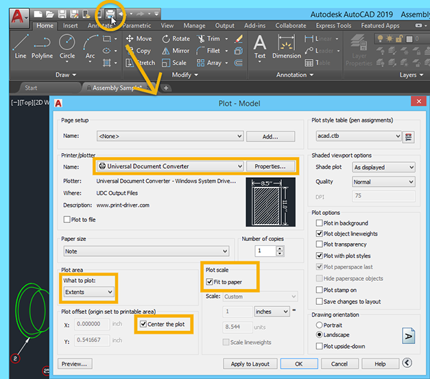
- Export Your Drawing
- For DWG or DXF formats, use the SAVEAS command and choose the desired format from the drop-down menu.
- To create a PDF, go to the Output tab and select \"Plot.\" Choose \"DWG to PDF.pc3\" as the printer/plotter device. Adjust the paper size, plot area, and other settings as needed, then click \"OK\" to create the PDF.
- Check the Exported Files
- After exporting, open the exported files in the appropriate software to ensure that all elements are displayed correctly and that the scale is accurate. This step is crucial for avoiding misunderstandings or errors when your drawing is viewed or printed by others.
By following these steps, you can ensure that your AutoCAD drawings are properly prepared and exported, ready for sharing, printing, or further processing. This process is essential for maintaining the integrity and professionalism of your work.
Embark on your AutoCAD journey with confidence, knowing you have the tools and techniques to bring your visions to life. This guide empowers you to create, refine, and share professional drawings, unlocking endless possibilities in design and drafting.