Topic autocad drawing units: Unlock the full potential of your AutoCAD designs by mastering drawing units, a foundational skill that enhances precision and efficiency in your projects.
Table of Content
- How to specify drawing units in AutoCAD?
- Understanding AutoCAD Drawing Units
- Setting Up Drawing Units in AutoCAD
- Converting Drawing Units in Existing Drawings
- Choosing Between Imperial and Metric Units
- Adjusting Units for Dimensioning
- YOUTUBE: Setting Units in Meters in AutoCAD Drawings
- Configuring Units for Layouts and Viewports
- Unit Precision and Its Impact on Drawing Accuracy
- Scaling Objects Correctly with Unit Changes
- Using the DWGUNITS Command for Unit Management
- Best Practices for Drawing Unit Configuration
How to specify drawing units in AutoCAD?
To specify the drawing units in AutoCAD, you can follow the steps below:
- Open AutoCAD and either create a new drawing or open an existing drawing.
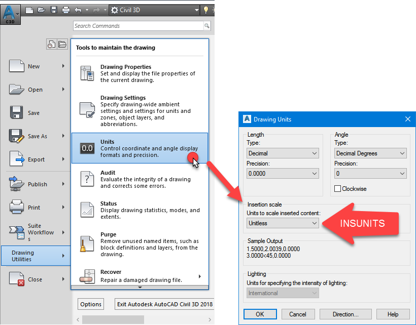
- Go to the \"Application menu\" (the red A icon in the top-left corner) and click on it.
- In the menu that appears, click on \"Drawing Utilities\" and then select \"Units...\" from the dropdown.
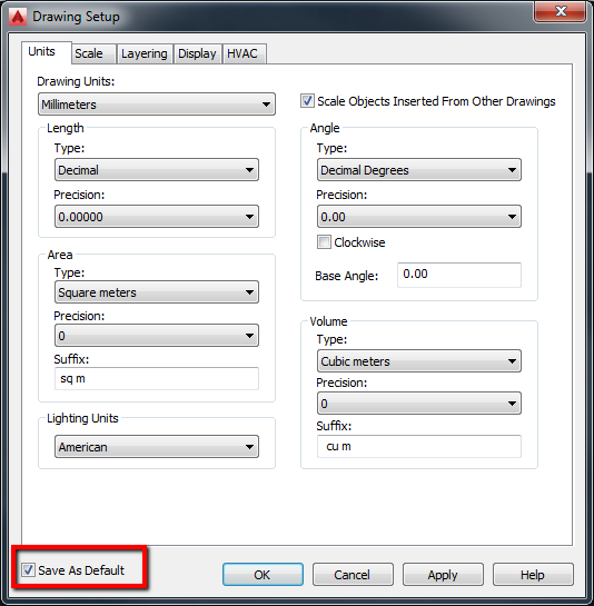
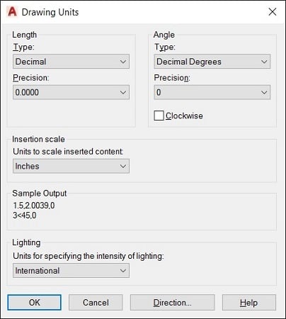
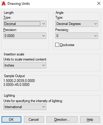
- A \"Drawing Units\" dialog box will open, allowing you to specify the units for your drawing.
- In the \"Insertion Scale\" section, you can choose your desired unit format from the \"Type\" dropdown menu. This includes options such as \"Inches\", \"Feet\", \"Millimeters\", \"Centimeters\", \"Meters\", etc.
- Next, choose the desired precision for your units by adjusting the values in the \"Precision\" section.
- If you want to adjust the scaling of existing objects to match the new units, you can check the \"Scale Objects Inserted from Other Drawings\" checkbox.
- After making the necessary changes, click on the \"OK\" button to apply the new units setting to your drawing.
By following these steps, you can easily specify the drawing units in AutoCAD according to your preferences.
READ MORE:
Understanding AutoCAD Drawing Units
AutoCAD drawing units are the cornerstone of creating precise and scalable designs. These units define the measurement of distances, dimensions, and areas in your drawings, ensuring accuracy and consistency across various projects.
- Absolute Units: Refer to specific measurement systems like millimeters, inches, or meters.
- Relative Units: Used for proportions or ratios, allowing flexibility in design scaling.
Setting your drawing units correctly from the beginning is crucial as it affects how dimensions, text, and other elements appear and interact within your design.
- Navigate to the \"Format\" menu and select \"Units\" to open the Drawing Units dialog box.
- Choose your desired measurement system (imperial or metric) to set the drawing units.
- Adjust the precision to define how detailed your measurements should be.
- Consider the type of project to decide on the appropriate units and precision level.
Understanding and correctly setting up drawing units in AutoCAD not only streamlines the design process but also ensures that your projects meet exact specifications and standards.

Setting Up Drawing Units in AutoCAD
Configuring the drawing units in AutoCAD is a fundamental step to ensure your designs are accurate and to scale. Here\"s how to set up drawing units for your projects:
- Open the AutoCAD software and either start a new drawing or open an existing one.
- Access the command line by typing \"UNITS\" and pressing Enter, or navigate through the application menu to \"Drawing Utilities\" > \"Units\". This opens the \"Drawing Units\" dialog box.
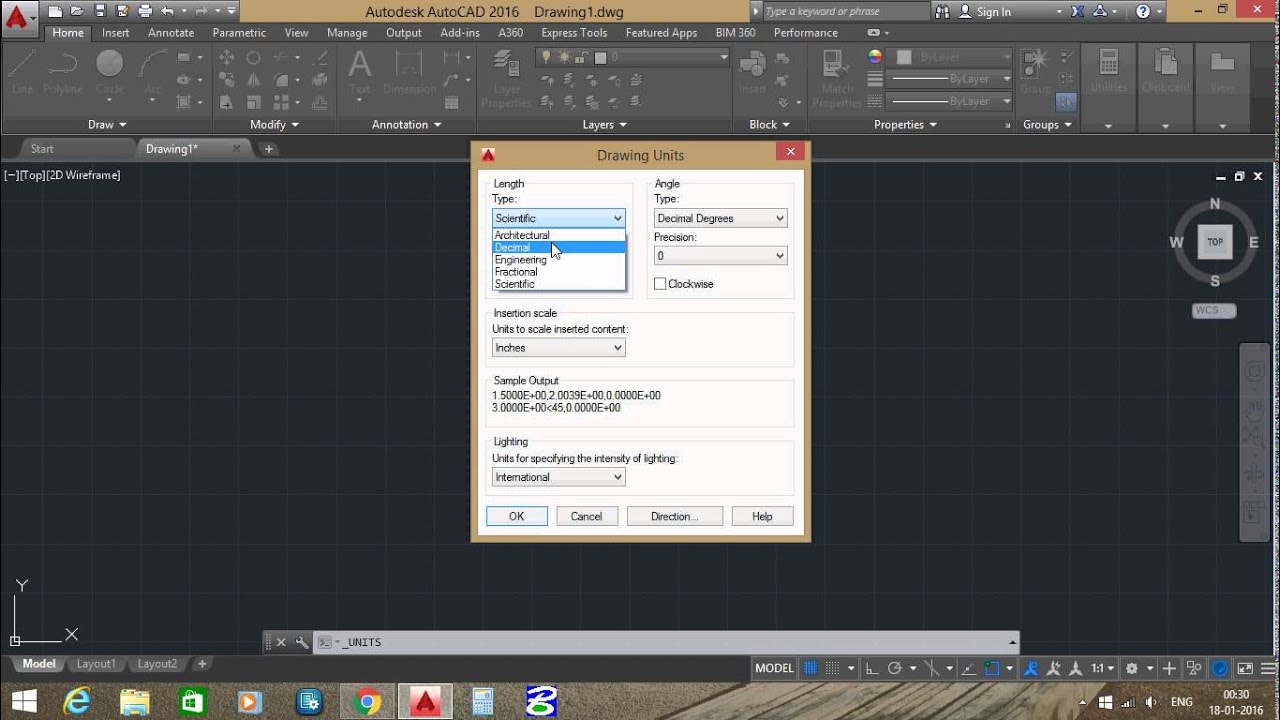
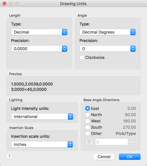
- In the \"Drawing Units\" dialog box, you\"ll see several options:
- Length: Choose your preferred unit of measure (e.g., millimeters, inches) for linear dimensions.
- Angle: Select the unit for measuring angles (e.g., degrees, radians).
- Precision: Define how precise your measurements should be, affecting how dimensions are displayed.
- After configuring your units and precision, click \"OK\" to apply the changes.
- Consider setting up a drawing template with your preferred units to streamline future projects.
Properly setting up drawing units in AutoCAD from the start of your project can save time and prevent scaling issues later on. Whether you work in architecture, engineering, or design, mastering this step is crucial for creating precise and professional drawings.

Converting Drawing Units in Existing Drawings
Occasionally, you might need to convert the units of an existing drawing in AutoCAD to meet new project requirements or standards. Here’s a step-by-step guide to efficiently perform this conversion:
- Open the drawing in AutoCAD.
- Type \"SCALE\" into the command line and press Enter. This command will prepare the drawing for scaling.
- Select all objects in the drawing by typing \"ALL\" and then pressing Enter.
- Specify the base point for the scale operation. Typically, you can select \"0,0\" (the origin point) for convenience.
- Enter the scale factor. This is determined by the ratio of the current units to the desired units. For example, if converting from inches to millimeters, the scale factor would be 25.4 (since there are 25.4mm in an inch).
- Press Enter to apply the scaling. All selected objects will be resized according to the specified scale factor, effectively converting the drawing units.
After scaling, it\"s advisable to check some dimensions to ensure the conversion has been successful. Remember, this method scales the geometry within your drawing but does not change the units setting in AutoCAD. You should manually adjust the units settings if necessary to reflect the new scale accurately.
Choosing Between Imperial and Metric Units
When starting a new project in AutoCAD, one of the first decisions you\"ll need to make is whether to use imperial or metric units. This choice depends on several factors including the project\"s geographical location, industry standards, and client requirements.
- Geographical Location: In the United States, the imperial system is commonly used, whereas most other countries use the metric system.
- Industry Standards: Certain industries may prefer one system over the other. For example, automotive and scientific fields often use metric units, while construction in the U.S. may use imperial units.
- Client Requirements: Always consider the client\"s needs. If the client operates in a country or industry that favors a particular unit system, it\"s best to adhere to that standard.
To choose the unit system in AutoCAD:
- Open the \"Units\" dialog box by typing \"UNITS\" into the command line and pressing Enter.
- Select \"Imperial\" or \"Metric\" from the Type drop-down menu, depending on your project needs.
- Adjust other settings such as precision and angle units as necessary.
- Click \"OK\" to apply your settings.
Remember, consistency is key. Once you\"ve chosen a unit system, stick with it throughout the project to avoid confusion and errors in your design.
_HOOK_
Adjusting Units for Dimensioning
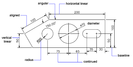
Dimensioning is a critical aspect of any AutoCAD drawing, providing detailed measurements that ensure the design can be accurately realized. Adjusting units for dimensioning involves several steps to ensure your dimensions reflect the intended measurements and standards.
- Open your drawing and ensure the correct drawing units are set for your project.
- Access the Dimension Style Manager by typing \"DIMSTYLE\" into the command line and pressing Enter, or by navigating to Annotate > Dimensions > Dimension Style on the ribbon.
- In the Dimension Style Manager, create a new style or modify an existing one. This includes setting the correct units, precision, and appearance for your dimensions.
- Within the Dimension Style Manager, you can adjust:
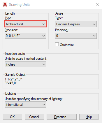
- Linear Units: Choose how linear measurements are displayed, including the format (e.g., decimal, architectural) and precision.
- Angular Units: Set how angles will be measured and displayed, selecting the format and precision.
- Text Placement: Customize where and how the dimension text appears relative to the dimension lines and arrows.
- Arrowheads: Select the style and size of arrowheads to mark the ends of the dimension lines.
- Apply your changes and set the new or modified style as current to ensure all new dimensions use these settings.
By meticulously adjusting units for dimensioning, you can ensure that your AutoCAD drawings convey the exact specifications necessary for accurate construction, manufacturing, or fabrication, aligning with industry standards and project requirements.
Setting Units in Meters in AutoCAD Drawings
Discover the power of AutoCAD and dive into a world of limitless creativity. Watch this captivating video to learn how to master the software and create stunning designs like never before!
Setting Drawing Units and Limits in AutoCAD
Want to enhance your drawing skills? This video is a must-watch! Explore the concept of drawing units and unlock the secrets to precise and accurate measurements. Embrace the world of drawing with confidence!
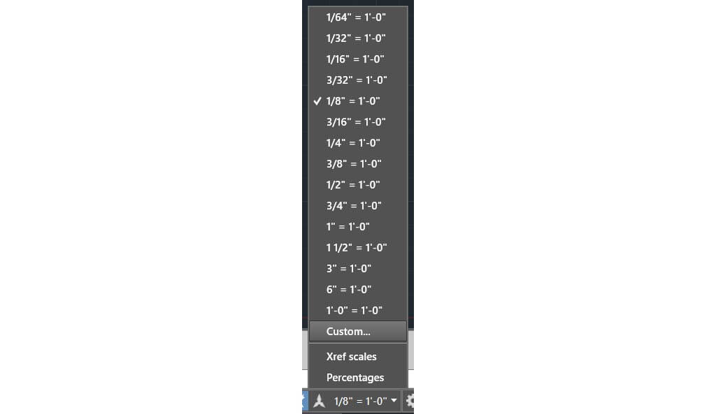
Configuring Units for Layouts and Viewports
Configuring units for layouts and viewports is essential for presenting your AutoCAD drawings accurately on paper or in digital format. This process ensures that the scale and dimensions of your design are correctly represented in the layout views.
- Start by opening your drawing in AutoCAD and switch to the layout tab you wish to configure.
- Create or select a viewport within the layout. Double-click inside the viewport to activate it.
- Once inside the viewport, type \"UNITS\" into the command line and press Enter. This ensures that the units within the viewport match those of the model space.
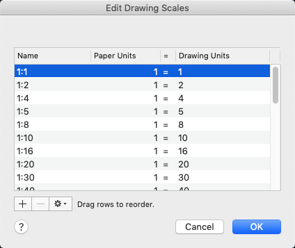
- Adjust the scale of the viewport to reflect the desired scale for printing or presentation. This is done by selecting the viewport, then using the properties panel to specify the standard scale.
- If necessary, customize the dimension style within the viewport to ensure dimensions are legible and appropriate for the scale. This might involve adjusting text size, arrowheads, or other dimension settings.
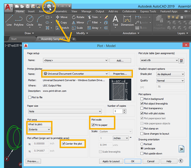
- Ensure that the layout settings, such as paper size and plot scale, are correctly set up to match the scale and dimensions of the viewport. This is crucial for accurate printouts or PDF exports.
By carefully configuring units for layouts and viewports, you can achieve precise representation of your design in presentations and printed materials, ensuring clarity and professionalism in your AutoCAD projects.
Unit Precision and Its Impact on Drawing Accuracy
The precision of units in AutoCAD drawings plays a crucial role in the accuracy and quality of the final design. Setting the right level of unit precision ensures that measurements are exact, reducing errors and discrepancies in construction or manufacturing.
- Impact on Design: High precision is essential for complex designs where small errors can accumulate, leading to significant issues in the physical realization of a project.
- Communication: Precise units facilitate clear communication of design intent to contractors, fabricators, and team members, minimizing misunderstandings.
- Modification and Scaling: Correct unit precision allows for easier modifications and scaling of designs, ensuring that changes maintain dimensional accuracy.
To adjust unit precision in AutoCAD:
- Open the \"Units\" dialog box by typing \"UNITS\" in the command line and pressing Enter.
- In the dialog box, find the \"Precision\" dropdown for both length and angle units. Select the level of precision that matches the needs of your project.
- Consider the project\"s scale and the level of detail required when choosing precision. For engineering drawings, higher precision might be necessary, while for architectural plans, a lower precision may suffice.
- Review and adjust dimension styles to ensure that the chosen precision is reflected in the dimensioning of your drawings.
Ultimately, setting the appropriate unit precision is a balance between ensuring accuracy and maintaining readability and manageability of the drawing. By carefully selecting the level of precision, you can significantly enhance the accuracy and reliability of your AutoCAD projects.
Scaling Objects Correctly with Unit Changes
When changing units in AutoCAD, ensuring that objects are scaled correctly is vital to maintaining the integrity and accuracy of your design. A proper scale adjustment ensures that all elements of your drawing correspond accurately to the real-world dimensions they represent.
- Identify the current and desired units of your drawing to determine the scale factor needed for conversion. For instance, converting from inches to millimeters requires a scale factor of 25.4.
- Select the objects you need to scale. You can select objects individually, by layer, or use the \"Select All\" command for a global scale adjustment.
- Use the \"SCALE\" command by typing it into the command line and pressing Enter. Then, specify the base point for the scaling operation. A common choice is the origin point (0,0), but any point can be used depending on your needs.
- Enter the scale factor calculated in step 1 when prompted. This will resize your selected objects accordingly.
It\"s essential to apply the correct scale factor to avoid distortions or inaccuracies in your drawing. Additionally, after scaling, double-check dimensions and adjust any annotations or text elements to ensure they are still correct and legible.
- Note: When scaling objects, consider the impact on associated elements like dimensions and text. These may need to be adjusted separately to maintain readability and accuracy.
Correctly scaling objects with unit changes in AutoCAD is a critical step in ensuring that your designs remain precise and true to your intentions, whether you are working on architectural, engineering, or design projects.
Using the DWGUNITS Command for Unit Management
The DWGUNITS command in AutoCAD is a powerful tool for managing drawing units, especially useful when importing or exporting drawings with different units. It helps ensure that all elements within a drawing are correctly scaled relative to the chosen unit of measurement.
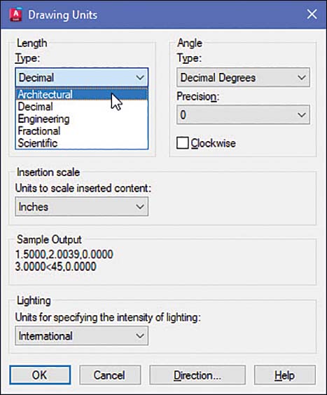
- Type \"DWGUNITS\" into the command line and press Enter to open the Drawing Units dialog box.
- The dialog box will prompt you to select the type of units used in the drawing. Options include architectural, decimal, engineering, fractional, and scientific. Choose the one that matches your project requirements.
- After selecting the unit type, you\"ll be asked to specify the insertion scale. This determines how objects from other drawings will be scaled when inserted into your current drawing. Choose the unit that corresponds to the one you\"re using in your project.
- You will also have the option to scale objects from other drawings upon insertion. AutoCAD can automatically scale incoming objects to match the current drawing\"s units, ensuring consistency.
- Confirm your settings by selecting \"OK\". These settings will now be applied to your drawing, aiding in unit management and consistency across imported and exported content.
Using the DWGUNITS command effectively streamlines the process of managing units in your drawings, allowing for seamless integration of content from various sources and ensuring that your projects remain accurate and to scale.
- Note: It\"s important to understand the implications of changing units on existing drawings, as it may affect dimensions and scaling. Always double-check your work after applying changes.
The DWGUNITS command is an essential tool for AutoCAD users, facilitating precise and efficient unit management across diverse projects and collaborations.
_HOOK_
READ MORE:
Best Practices for Drawing Unit Configuration
Effective drawing unit configuration in AutoCAD is essential for the accuracy and success of your projects. Following best practices ensures that your designs are precise, easily understandable, and compatible with the standards of your industry. Here are key guidelines to follow:
- Understand the Project Requirements: Before starting, clarify the unit system (metric or imperial) and precision needed based on the project\"s scope, industry standards, and client specifications.
- Consistency Across Drawings: Maintain consistency in unit settings across all related drawings to avoid confusion and errors during the design process.
- Use AutoCAD Templates: Create or use existing templates with predefined unit settings to streamline the setup process for new projects.
- Check Units for Imported Content: When importing content from other drawings or external sources, ensure the units match your current project settings to avoid scaling issues.
- Regularly Review Unit Settings: Periodically check the unit settings in your drawings, especially before sharing with clients or collaborators, to ensure they meet the intended specifications.
- Train Team Members: Ensure all team members are familiar with the importance of correct unit configuration and how to apply these settings in AutoCAD, promoting consistency and accuracy in your team\"s output.
By adhering to these best practices, you can enhance the efficiency of your design process, reduce the risk of errors, and ensure your drawings accurately represent your design intentions, facilitating smooth collaboration and project execution.
Mastering AutoCAD drawing units is foundational for creating precise, professional designs. By applying the outlined best practices, you can ensure accuracy and efficiency, elevating your projects to the next level.