Topic autocad tutorial for mechanical engineering: Embark on a journey to master AutoCAD for mechanical engineering with our comprehensive tutorials, designed to equip you with essential design and drafting skills for a successful career.
Table of Content
- What are some AutoCAD tutorial resources specifically tailored for mechanical engineering?
- Getting Started with AutoCAD for Mechanical Engineering
- Understanding the AutoCAD Interface and Basic Operations
- 2D Drafting Techniques for Mechanical Engineers
- Creating 3D Models and Simulations in AutoCAD
- Advanced 3D Modeling Techniques for Mechanical Design
- Generating Detailed Drawings and Documentation
- YOUTUBE: AutoCAD Tutorial for Mechanical Engineering
- Using AutoCAD\"s Finite Element Analysis for Mechanical Engineering
- Efficiently Managing Libraries of Standard Parts
- Parametric Modeling and Its Applications in Mechanical Engineering
- Kinematic Analysis for Simulating Mechanical Movements
- Collaborative Tools and Sharing Designs in AutoCAD
- Customizing AutoCAD for Mechanical Engineering Tasks
- Best Practices and Tips for Mechanical Design in AutoCAD
- Preparing for the Job Market: Skills and Certifications
What are some AutoCAD tutorial resources specifically tailored for mechanical engineering?
Here are some AutoCAD tutorial resources specifically tailored for mechanical engineering:
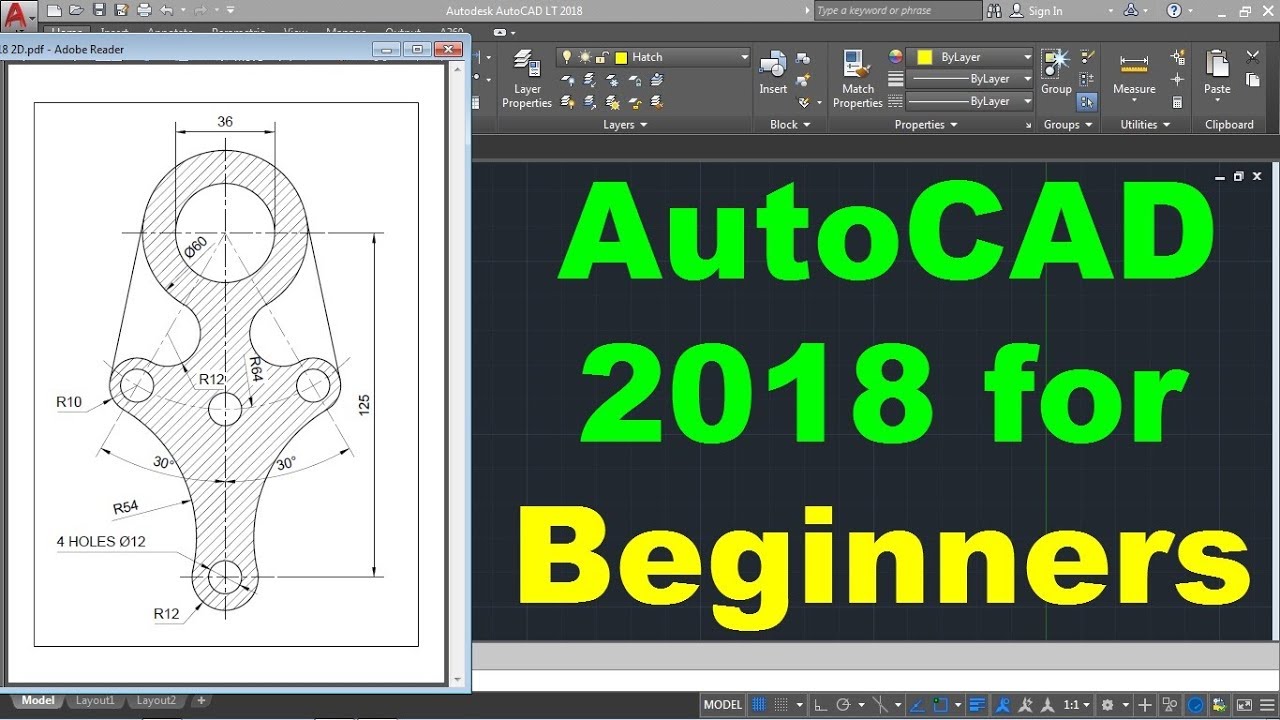
- AutoCAD Mechanical Tutorial for Beginners - YouTube: This video tutorial series on YouTube provides a step-by-step guide for beginners to learn AutoCAD Mechanical, covering essential tools and techniques.
- CADTutor Mechanical Tutorials: CADTutor offers a range of mechanical engineering tutorials for AutoCAD, including topics like creating 2D mechanical drawings, dimensioning, creating and managing blocks, and more.
- Tutorial45 AutoCAD for Mechanical Engineering: This tutorial series provides comprehensive guidance on using AutoCAD specifically for mechanical engineering tasks, such as creating 3D models, assembling parts, generating technical drawings, and more.
- GrabCAD Mechanical Tutorials: GrabCAD offers a collection of mechanical engineering tutorials for different software, including AutoCAD. These tutorials cover a wide range of topics, including modeling, drafting, and simulating mechanical designs.
- Udemy AutoCAD Courses: Udemy offers various AutoCAD courses specifically designed for mechanical engineers. These courses provide in-depth knowledge of AutoCAD tools, features, and functionalities for mechanical engineering purposes.
READ MORE:
Getting Started with AutoCAD for Mechanical Engineering
Beginning your journey in AutoCAD for mechanical engineering opens up a world of design and drafting capabilities. This section aims to guide beginners through the initial steps of using AutoCAD, focusing on fundamental concepts and tools essential for mechanical engineering projects.
- Understanding the AutoCAD Interface: Familiarize yourself with the AutoCAD workspace, including the ribbon, toolbars, command line, and drawing area. Knowing where tools are located and how to access commands efficiently is crucial.
- Setting Up Your First Project: Learn how to create a new drawing file, set drawing units, and understand the importance of scale. This step is foundational for accurate mechanical design.
- Basic Drawing and Editing Commands: Practice with basic commands like LINE, CIRCLE, RECTANGLE, TRIM, and EXTEND. These commands are the building blocks for creating mechanical components.
- Layer Management: Layers are essential for organizing your drawing. Learn how to create, modify, and manage layers to keep your projects organized and efficient.
- Dimensioning and Annotation: Accurate dimensions and annotations are critical in mechanical engineering drawings. Explore how to use dimensioning tools and add text annotations to your designs.
- Creating Simple Mechanical Drawings: Apply the skills you\"ve learned to draw a basic mechanical part. This exercise will help reinforce your understanding of AutoCAD tools and their application in mechanical engineering.
Remember, practice is key to becoming proficient in AutoCAD. By following these steps, you will start building the foundation needed to tackle more complex mechanical engineering projects.

Understanding the AutoCAD Interface and Basic Operations
Mastering the AutoCAD interface and its basic operations is crucial for anyone looking to excel in mechanical engineering design. This section will guide you through the interface components and essential operations to kickstart your projects with confidence.
- Navigating the AutoCAD Workspace: Begin by familiarizing yourself with the AutoCAD workspace. The workspace includes the drawing area, command line, navigation tools, and various palettes. Understanding these elements is key to efficiently using AutoCAD.
- Using the Ribbon: The ribbon at the top contains multiple tabs, each with its own set of tools. Learn how to navigate these tabs to access drawing tools, modification commands, and other features relevant to mechanical engineering.
- Command Line Fundamentals: The command line is a powerful feature for executing commands. Practice entering commands directly and using keyboard shortcuts to improve your speed and efficiency.
- Basic Drawing Tools: Get hands-on with basic drawing tools such as lines, circles, arcs, and rectangles. These are the foundation of any mechanical drawing and essential for creating engineering designs.
- Modifying Objects: Learn how to select, move, copy, rotate, and scale objects. Mastering these commands will enable you to edit your designs easily and accurately.
- Understanding Layers: Layers organize your drawing by separating different elements. Learn how to create and manage layers, set layer properties, and use them to enhance the clarity and organization of your drawings.
- Dimensioning and Annotations: Dimensions and annotations provide necessary information about your design. Explore how to add dimensions, leaders, and text to your drawings to communicate details effectively.
- Zooming and Panning: Efficiently navigate your drawing by zooming and panning. Master these views to work more effectively on detailed sections or the overall drawing.
By understanding these fundamental aspects of the AutoCAD interface and operations, you\"ll be better prepared to tackle mechanical engineering projects with precision and efficiency.

2D Drafting Techniques for Mechanical Engineers
2D drafting is a cornerstone of mechanical engineering design, offering a detailed representation of components and assemblies. This section delves into essential techniques and practices to enhance your drafting skills in AutoCAD.
- Setting Up the Drawing Environment: Start by configuring your drawing environment. Adjust units, drawing limits, and grid settings to match the scale and precision required for your mechanical design projects.
- Layer Management: Efficiently use layers to organize different aspects of your drawings, such as dimensions, text, and main geometry. Assign colors, linetypes, and lineweights to layers for better clarity and visualization.
- Creating Precise Geometry: Learn to use AutoCAD’s geometric construction tools such as OFFSET, FILLET, and CHAMFER to create accurate and detailed mechanical parts. Utilizing object snaps (OSNAP) for precision is crucial.
- Dimensioning: Master the art of dimensioning, a critical step to convey the size and tolerance of parts. Explore the use of linear, radial, angular, and ordinate dimensions to provide clear and comprehensive specifications.
- Applying Text and Annotations: Annotations add necessary information to your drawings. Incorporate text, leaders, and tables to describe parts, list specifications, or provide assembly instructions.
- Using Blocks and Symbols: Streamline your workflow by creating and using blocks for frequently used components. This practice saves time and ensures consistency across different drawings.
- Drafting Views: Develop proficiency in creating standard views (top, front, side) and auxiliary views for more complex parts. Understanding projection methods is key to accurate mechanical drafting.
- Plotting and Publishing: Finalize your drawing with proper plotting settings, including paper size, scale, and plot style tables. Learn how to publish your drawings in various formats for sharing and printing.
Adopting these 2D drafting techniques in AutoCAD will significantly improve the quality and efficiency of your mechanical engineering designs, laying a strong foundation for advanced 3D modeling.
Creating 3D Models and Simulations in AutoCAD
2D drafting is a cornerstone of mechanical engineering design, offering a detailed representation of components and assemblies. This section delves into essential techniques and practices to enhance your drafting skills in AutoCAD.
- Setting Up the Drawing Environment: Start by configuring your drawing environment. Adjust units, drawing limits, and grid settings to match the scale and precision required for your mechanical design projects.
- Layer Management: Efficiently use layers to organize different aspects of your drawings, such as dimensions, text, and main geometry. Assign colors, linetypes, and lineweights to layers for better clarity and visualization.
- Creating Precise Geometry: Learn to use AutoCAD’s geometric construction tools such as OFFSET, FILLET, and CHAMFER to create accurate and detailed mechanical parts. Utilizing object snaps (OSNAP) for precision is crucial.
- Dimensioning: Master the art of dimensioning, a critical step to convey the size and tolerance of parts. Explore the use of linear, radial, angular, and ordinate dimensions to provide clear and comprehensive specifications.
- Applying Text and Annotations: Annotations add necessary information to your drawings. Incorporate text, leaders, and tables to describe parts, list specifications, or provide assembly instructions.
- Using Blocks and Symbols: Streamline your workflow by creating and using blocks for frequently used components. This practice saves time and ensures consistency across different drawings.
- Drafting Views: Develop proficiency in creating standard views (top, front, side) and auxiliary views for more complex parts. Understanding projection methods is key to accurate mechanical drafting.
- Plotting and Publishing: Finalize your drawing with proper plotting settings, including paper size, scale, and plot style tables. Learn how to publish your drawings in various formats for sharing and printing.
Adopting these 2D drafting techniques in AutoCAD will significantly improve the quality and efficiency of your mechanical engineering designs, laying a strong foundation for advanced 3D modeling.

_HOOK_
Advanced 3D Modeling Techniques for Mechanical Design
Advancing from basic 3D modeling to sophisticated mechanical design requires mastery of several advanced techniques in AutoCAD. This section explores the essential advanced 3D modeling techniques that mechanical engineers can leverage to create complex, precise, and efficient designs.
- Surface Modeling: Surface modeling allows the creation of complex geometries with smooth surfaces. Learn to use commands like 3DSURF, NETWORK, and SWEEP to generate intricate designs that are difficult to create with solid modeling alone.
- Solid Modeling Enhancements: Enhance your solid modeling skills by utilizing Boolean operations, such as UNION, SUBTRACT, and INTERSECT, to combine or modify 3D solids. Mastering these operations is crucial for creating complex assemblies and components.
- Parametric Constraints: Apply parametric constraints to control dimensions and geometric relationships between objects. This technique ensures that your designs adapt to changes while maintaining their integrity and predefined constraints.
- Advanced Assembly Modeling: Focus on advanced assembly modeling techniques, including the use of mechanical constraints and joints to simulate real-world movement and interaction between parts.
- Custom Materials and Rendering: Learn how to create custom materials and utilize rendering techniques to produce realistic images of your mechanical designs. This skill is invaluable for presentations and design verification.
- Finite Element Analysis (FEA): Although primarily a simulation tool, understanding the basics of FEA in AutoCAD can help you predict how designs will perform under various conditions, thus informing your modeling decisions.
- Automation with AutoLISP: Automate repetitive tasks and customize AutoCAD functionality with AutoLISP. Writing simple scripts can significantly speed up your design process.
By mastering these advanced techniques, mechanical engineers can significantly enhance the quality, efficiency, and functionality of their designs in AutoCAD. Each of these skills opens new possibilities for innovation and problem-solving in mechanical design.
Generating Detailed Drawings and Documentation
Creating detailed drawings and comprehensive documentation is a crucial step in the design process for mechanical engineers. AutoCAD facilitates this with powerful tools that ensure precision, clarity, and compliance with industry standards. Here’s how to effectively generate detailed drawings and documentation in AutoCAD:
- Setting Up Your Drawing: Begin by setting the correct scale and paper size for your drawing. Use the LAYOUT command to create a new layout and specify the PLOT settings to match your documentation requirements.
- Creating Views: Use the VIEWBASE command to generate 2D views from 3D models. Specify the type of projection (e.g., orthogonal, isometric) and select the views you need, including front, top, side, and auxiliary views.
- Dimensioning: Apply dimensions to your drawings accurately with the DIM command. AutoCAD offers various dimensioning tools, including linear, aligned, radial, diameter, and angular, to help convey the exact size and geometry of your design.
- Adding Annotations: Annotations are essential for conveying additional information that cannot be represented graphically. Use the TEXT command for textual information and the LEADER command to point out specific parts of your design.
- Creating Bill of Materials (BOM): For assemblies, a BOM is crucial. Use the DATAEXTRACTION command to generate a BOM. This tool allows you to extract information from your drawing and present it in a table format, listing parts, materials, and other critical details.
- Using Layers: Organize your drawing by assigning different elements to layers. This practice not only keeps your drawing tidy but also makes it easier to manage visibility and print settings for various components of your design.
- Generating Section and Detail Views: Use the SECTIONPLANE and DETAIL commands to create detailed section and detail views. These views are essential for showing internal features of your design that are not visible in standard views.
- Finalizing and Printing: Before finalizing your drawing, check for accuracy and completeness. Use the PUBLISH command to batch plot multiple drawings or layouts. Ensure that all settings match the requirements for printing or digital sharing.
By following these steps, mechanical engineers can produce detailed drawings and documentation that are essential for manufacturing, patent applications, and technical communication. AutoCAD’s comprehensive toolset makes it easier to achieve precision and efficiency in this critical task.

AutoCAD Tutorial for Mechanical Engineering
AutoCAD: Explore the limitless possibilities of design with AutoCAD! Unleash your creativity and bring your ideas to life with this powerful software. Watch our video to learn the ins and outs of AutoCAD and discover how it can transform your projects like never before.
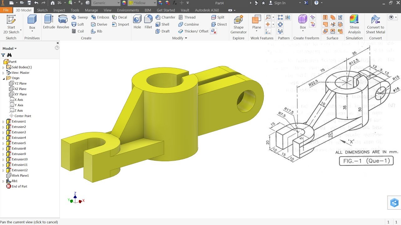
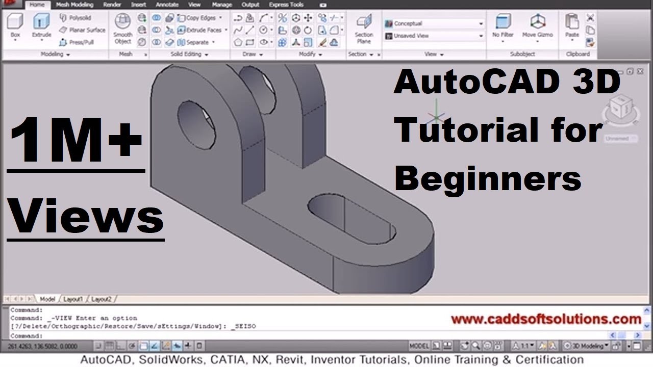
AutoCAD 3D Practice Mechanical Drawing using Box and Cylinder Command | AutoCAD 3D Modeling Mechanical
3D Modeling: Dive into the fascinating world of 3D modeling and witness your imagination come to life! From architectural designs to character animations, this video will guide you through the intricacies of 3D modeling, allowing you to create stunning visuals that will leave you in awe. Don\'t miss out on this opportunity to unlock a whole new dimension of creativity!
Using AutoCAD\"s Finite Element Analysis for Mechanical Engineering
Finite Element Analysis (FEA) is a critical tool for mechanical engineers, enabling them to simulate and analyze the behavior of their designs under various conditions. AutoCAD\"s FEA capabilities allow engineers to assess performance, identify potential issues, and make informed decisions to improve design quality. Here\"s how to effectively utilize FEA in AutoCAD for mechanical engineering:
- Preparing Your Model: Begin by ensuring your 3D model is suitable for analysis. This means simplifying the geometry where possible, removing unnecessary details that do not affect the analysis, and ensuring the model is a solid or watertight mesh.
- Defining Material Properties: Assign material properties to different parts of your model. This includes density, elasticity, and thermal properties, which are crucial for accurate analysis results. Use the MATERIAL command to access AutoCAD\"s material library or to define custom materials.
- Applying Loads and Constraints: Identify and apply the forces, pressures, and constraints that your design will encounter in real-world operation. Accurately representing these factors is key to obtaining meaningful analysis results.
- Meshing: Convert your model into a finite element mesh using AutoCAD\"s meshing tools. The mesh quality significantly impacts the accuracy of the analysis. A finer mesh may increase accuracy but will also require more computational resources.
- Running the Analysis: With your model prepared, material properties defined, and loads and constraints applied, you\"re ready to run the analysis. Monitor the process for any errors or issues that may arise, adjusting your model or settings as necessary.
- Interpreting Results: After the analysis is complete, review the results to understand the performance of your design. Look for areas of high stress, deformation, or failure that may require design modifications.
- Iterating on Design: Use the insights gained from the FEA to make informed changes to your design. This iterative process may involve adjusting dimensions, changing materials, or modifying the geometry to improve performance and reliability.
- Documenting the Analysis: Finally, document your analysis process and results. Include details about the model preparation, analysis settings, and any conclusions or design changes made as a result. This documentation is vital for future reference and for validation purposes.
By incorporating FEA into the design process, mechanical engineers can enhance the reliability, performance, and safety of their products. AutoCAD\"s tools make it accessible to perform these complex analyses, empowering engineers to make data-driven design decisions.
Efficiently Managing Libraries of Standard Parts
Managing libraries of standard parts in AutoCAD is essential for mechanical engineers to streamline their design processes, ensure consistency, and reduce design times. A well-organized library allows for easy access to commonly used components, facilitating their integration into new designs. Here\"s how to efficiently manage libraries of standard parts in AutoCAD:
- Creating a Library Structure: Begin by establishing a clear and logical folder structure for your library. Organize parts by category, such as fasteners, gears, or bearings. This structure makes it easier to locate and update components.
- Standardizing Part Names: Develop a naming convention for your parts that is descriptive and consistent. This might include information on part size, material, and unique identifiers. A standardized naming system simplifies the search and insertion of parts into your designs.
- Using Block Libraries: Convert your standard parts into blocks. Blocks in AutoCAD allow you to insert parts as single objects, which can then be easily manipulated and reused across multiple projects. Utilize the BLOCK command to create and define your parts as blocks.
- Implementing Dynamic Blocks: For parts that come in various sizes or configurations, consider using dynamic blocks. Dynamic blocks contain parameters and actions that allow for on-the-fly adjustments of the part\"s dimensions or properties, reducing the need for multiple similar but slightly different block definitions.
- Adding Custom Properties: Use the ATTDEF command to add custom properties to your blocks, such as part number, manufacturer, or material. These properties can be extracted for use in documentation, bills of materials, or inventory management.
- Maintaining Your Library: Regularly update your library to include new parts and remove obsolete ones. Keeping your library current ensures that designs are based on available and standard components, facilitating easier manufacturing and assembly.
- Sharing and Collaboration: If working in a team, make your parts library accessible to all team members. Use network drives or cloud storage solutions that support AutoCAD file types for easy sharing and updating of the library.
- Training and Documentation: Provide training or documentation on how to use and contribute to the parts library. Ensuring that all team members are familiar with the library’s structure and standards will enhance efficiency and consistency across designs.
By efficiently managing libraries of standard parts, mechanical engineers can significantly reduce the time and effort required to create new designs, ensuring that projects are completed faster and with greater accuracy.

Parametric Modeling and Its Applications in Mechanical Engineering
Parametric modeling is a powerful design approach in mechanical engineering that uses parameters to define shapes and geometries of parts and assemblies. This method allows engineers to quickly modify designs by simply changing the parameter values. AutoCAD supports parametric modeling, enabling efficient design iterations, optimization, and customization. Here\"s how parametric modeling is applied in mechanical engineering using AutoCAD:
- Defining Parameters: Start by defining the parameters that will control your design. These can be dimensions (length, width, height), angles, or any other geometric property. Use the PARAMETER command to create and manage these parameters within AutoCAD.
- Creating Geometric Constraints: Apply geometric constraints to your model to establish relationships between different elements. For example, you can specify that two lines remain perpendicular or that a circle stays tangent to a line regardless of changes in other parameters.
- Applying Dimensional Constraints: Dimensional constraints are used to control the size of the model\"s features. By linking dimensions to your defined parameters, you can quickly adjust the size and proportions of your design by changing the parameter values.
- Modeling with Parameters: With your parameters and constraints in place, begin modeling your part or assembly. As you create each feature, use the constraints and parameters to control its geometry. This approach ensures that all elements of your design are interrelated and can be adjusted easily.
- Automating Design Variations: Parametric modeling excels in creating families of parts or assemblies that share a common design but differ in dimensions or configurations. By adjusting the parameters, you can generate multiple variations of a design quickly and efficiently.
- Optimizing Designs: Use parametric modeling to explore different design options and perform optimizations. By changing parameters and observing the effects on performance or other criteria, you can identify the optimal design configuration.
- Integration with Analysis Tools: Parametric models can be directly used with analysis tools, such as finite element analysis (FEA) software, to evaluate the performance of designs under various conditions. This integration allows for a seamless design and analysis workflow.
- Documenting and Sharing: AutoCAD allows you to document your parametric models with detailed drawings and share them with team members or stakeholders. The parametric information can be retained, ensuring that others can understand and modify the design as needed.
Parametric modeling in AutoCAD streamlines the mechanical design process, from conceptualization to documentation. By leveraging this approach, engineers can achieve greater design flexibility, efficiency, and accuracy, leading to improved outcomes in their mechanical engineering projects.

_HOOK_
Kinematic Analysis for Simulating Mechanical Movements
Kinematic analysis is essential in mechanical engineering for understanding and simulating the movement of mechanisms and machines. While AutoCAD is primarily a design tool, it can be integrated with other software to perform kinematic analysis, helping engineers visualize and analyze motion within their designs. Here’s how you can approach kinematic analysis for simulating mechanical movements:
- Understanding Kinematic Concepts: Begin with a solid understanding of kinematic principles, such as velocity, acceleration, and the kinematic chains that constitute mechanisms. This foundational knowledge is crucial for setting up accurate simulations.
- Model Preparation: Prepare your AutoCAD model by ensuring that it accurately represents the mechanical assembly you wish to analyze. Simplify the model if necessary to focus on the moving parts and joints that are crucial for the kinematic study.
- Defining Joints and Constraints: Identify and define the joints (e.g., hinges, sliders, ball joints) within your assembly. These definitions are critical for simulating how parts will move in relation to one another.
- Exporting the Model: Export your AutoCAD model to a kinematic analysis software or a CAD package that supports motion simulation. Ensure that the exported model retains the necessary details for accurate analysis.
- Setting Up the Simulation: In the kinematic analysis software, set up the simulation by applying forces, defining motion parameters, and specifying any external constraints that affect the movement of the assembly.
- Running Simulations: Run the simulation to observe the movement of the assembly. Analyze the motion to identify any potential issues, such as collisions, excessive stress points, or inefficient movements.
- Iterating Design Based on Analysis: Use the insights gained from the simulation to refine your design. Adjust the geometry, reposition components, or change joint types as needed to optimize the mechanism’s performance.
- Visualization and Documentation: Finally, document your findings and use visualization tools within the kinematic analysis software to create animations or diagrams that illustrate the mechanism\"s movement. These visuals can be invaluable for presentations, reports, or further design iterations.
By integrating AutoCAD with kinematic analysis tools, mechanical engineers can more effectively simulate and analyze mechanical movements, leading to better-informed design decisions and more efficient mechanisms.
Collaborative Tools and Sharing Designs in AutoCAD
Collaboration is key in the field of mechanical engineering, where designs often require input from multiple stakeholders. AutoCAD provides a suite of collaborative tools and features that enable engineers to share, review, and co-edit designs seamlessly. Here\"s how to leverage these tools for effective collaboration:
- AutoCAD Web and Mobile: Use AutoCAD Web and Mobile applications to access and edit drawings from anywhere, on any device. This flexibility allows team members to make quick updates or reviews without needing access to the full desktop application.
- Sharing Drawings: Share your drawings directly from AutoCAD with the SHARE command, which generates a link that can be sent to colleagues, allowing them to view or edit the drawing in the AutoCAD Web app.
- Cloud Storage Integration: AutoCAD integrates with cloud storage services like Autodesk Drive, Dropbox, Google Drive, and Microsoft OneDrive. Save your drawings in the cloud for easy access and sharing among team members.
- Collaboration for Revit: For projects involving both mechanical engineering and architecture, Collaboration for Revit (C4R) enables multiple users to co-author Revit models stored in the cloud, ensuring that everyone has access to the latest version.
- Reference Manager: Use the Reference Manager for managing external references (Xrefs) when multiple users are working on interconnected parts of a project. This ensures that all references are up-to-date and correctly aligned across different drawings.
- Design Feedback: Collect feedback directly on your drawings using the MARKUP command. Stakeholders can add comments and markups without altering the original drawing, facilitating clear and efficient communication.
- Version Control: Keep track of changes and versions with AutoCAD’s version control capabilities. This is crucial for maintaining the integrity of the design and understanding the evolution of the project over time.
- Layer Management: Utilize layer management strategies to control the visibility of different aspects of your design when sharing with others. This allows stakeholders to focus on relevant information without being overwhelmed by the complexity of the entire drawing.
By effectively using these collaborative tools, mechanical engineers can enhance productivity, improve design accuracy, and ensure that all team members are aligned throughout the design process.
Customizing AutoCAD for Mechanical Engineering Tasks
Customizing AutoCAD can significantly enhance productivity and efficiency in mechanical engineering tasks. AutoCAD Mechanical toolset allows for the creation and customization of mechanical layers, offering precise control over mechanical design elements. The Mechanical Layer Manager, accessed through the AMLAYER command, provides a platform to manage layer properties and ensure consistency across your designs.
- Managing Mechanical Layers: Use the Mechanical Layer Manager to create and customize layers. This tool offers more advanced features compared to the standard Layer Manager, allowing for the definition and application of mechanical-specific properties to your layers.
- Creating Custom Commands: AutoCAD\"s interface can be customized to improve workflow efficiency. Create custom commands, toolbars, and ribbons through the Customize User Interface. This allows for quicker access to frequently used tools and commands, tailored to your specific workflow requirements.
- Programming in AutoCAD: Extend the capabilities of AutoCAD with AutoLISP programming. Write custom scripts to automate repetitive tasks, create complex geometry, or manage drawing properties, enhancing the software\"s functionality to meet specific mechanical engineering needs.
- Using Advanced Mechanical Design Tools: AutoCAD for Mechanical Design offers specialized tools for creating detailed 2D and 3D models of mechanical parts. Use commands like EXTRUDE, REVOLVE, and FILLET to build complex mechanical components and analyze them with simulation tools for ensuring structural integrity.
Remember to back up your customizations regularly and plan your custom interface carefully to avoid clutter and maintain a streamlined workflow. With these customizations, AutoCAD becomes an even more powerful tool, tailored to the specific demands of mechanical engineering projects.
Best Practices and Tips for Mechanical Design in AutoCAD
AutoCAD is a versatile and robust tool for mechanical engineering, offering a range of features and tools to enhance design precision, efficiency, and collaboration. Here are some best practices and tips to help you maximize your productivity in AutoCAD for mechanical design projects:
- Understand the Interface and Utilize Tools: Familiarize yourself with the AutoCAD interface, including the Ribbon, Quick Access Toolbar, Command Line, and Viewport Controls. Utilize these tools to navigate, draw, and modify your designs efficiently.
- Leverage Keyboard Shortcuts: Master commonly used keyboard shortcuts like “C” for circle, “L” for line, and “E” for erase. Keyboard shortcuts can significantly speed up your workflow and improve productivity.
- Use Layer States for Different Drawing Representations: Manage complex designs by creating and using different layer states. This allows you to switch between various drawing representations quickly, making it easier to work on specific aspects of your design without altering the entire project.
- Automate Tasks with Data Extraction: AutoCAD\"s data extraction capabilities allow you to automate the creation of reports such as schedules, part lists, and hole tables. Utilize these features to save time and ensure accuracy in your documentation.
- Customize Linetypes and Symbols: Create your own linetypes and symbols to match specific design standards or to fulfill unique project requirements. This customization can help maintain consistency and clarity across your mechanical drawings.
- Stay Informed with Online Resources: Enhance your skills and stay updated with the latest AutoCAD features and techniques by exploring online resources, forums, and tutorials. Engaging with the AutoCAD community can provide valuable insights and tips for your mechanical design projects.
Implementing these best practices and tips in your AutoCAD workflow can lead to more efficient and accurate mechanical designs. Embrace the power of AutoCAD\"s tools and features to bring your innovative mechanical engineering ideas to life.
READ MORE:
Preparing for the Job Market: Skills and Certifications
To thrive in the competitive job market of mechanical engineering, it\"s essential to acquire a blend of theoretical knowledge and practical skills. AutoCAD proficiency is crucial, and pursuing certifications like the AutoCAD Mechanical training and certification course can significantly boost your profile. These programs often provide hands-on exposure to real-world projects, ensuring you\"re not just theoretically sound but also practically proficient. By mastering AutoCAD and obtaining recognized certifications, you position yourself as a valuable asset to potential employers, standing out in a sea of candidates.
- Master AutoCAD Mechanical: Dive deep into AutoCAD Mechanical to understand its application in creating detailed and accurate mechanical designs.
- Obtain Recognized Certifications: Pursue industry-recognized certifications to validate your skills and stand out in the job market.
- Hands-on Project Experience: Engage in training programs that offer real-world project experience, ensuring your skills are tested and industry-ready.
- Continuous Learning: The field is ever-evolving, so stay updated with the latest trends, tools, and techniques in mechanical design and AutoCAD.
With a solid foundation in AutoCAD Mechanical, recognized certifications, practical experience, and a commitment to continuous learning, you\"ll be well-equipped to tackle the challenges of the mechanical engineering job market and build a successful career.
Explore our comprehensive AutoCAD tutorials for mechanical engineering, designed to elevate your design skills and boost your career prospects in the competitive industry.
_HOOK_