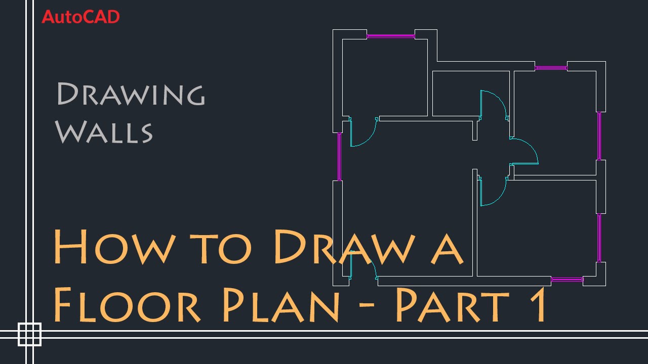
Topic floor plan autocad tutorial: Embark on your design journey with our comprehensive "Floor Plan AutoCAD Tutorial," perfect for beginners and pros alike, unlocking the secrets to mastering architectural layouts and elevating your drafting skills.
Table of Content
- How to create a floor plan in AutoCAD?
- Getting Started with AutoCAD for Floor Planning
- Setting Up Your Workspace and Units
- Basic Commands for Floor Plan Drawing
- Creating External Walls
- Drawing Internal Walls and Partitions
- Adding Doors and Windows
- YOUTUBE: Making a Simple Floor Plan in AutoCAD: Part 1 of 3
- Dimensioning Your Floor Plan
- Adding Furniture and Fixtures
- Floor Plan Drawing Techniques and Tips
- Finalizing and Exporting Your Floor Plan
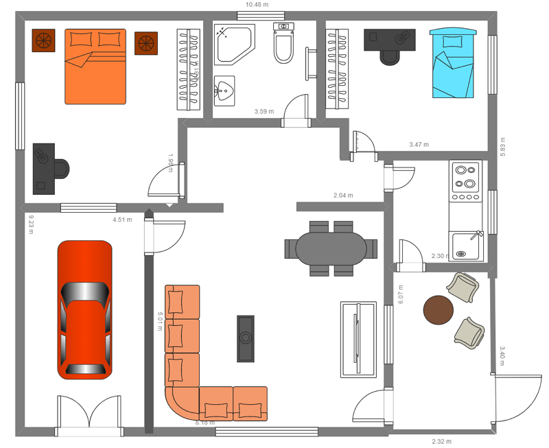
How to create a floor plan in AutoCAD?
Creating a floor plan in AutoCAD involves several steps. Here is a detailed guide:
- Open AutoCAD and create a new drawing file.
- Set the units of measurement for your drawing by typing \'UNITS\' in the command line and selecting the appropriate settings.
- Start drawing the outer walls of your floor plan by using the \'LINE\' command. Click on one corner of the wall, then click on the next corner, and so on until you have drawn all the walls.
- Use the \'OFFSET\' command to create the thickness of the walls. Type \'OFFSET\' in the command line, enter the desired thickness, and select the inner side of each wall.
- Add doors and windows by using the \'RECTANGLE\' command to draw rectangles at the appropriate locations. Then, use the \'TRIM\' command to trim the walls where the doors and windows intersect.
- Add dimensions to your floor plan by using the \'DIMENSION\' command. Click on the start point and end point of the dimension line, then enter the text value of the dimension.
- Add labels and annotations to your floor plan using the \'TEXT\' command. Click on the desired location, enter the text, and customize the font and size if necessary.
- You can also add furniture and other elements to your floor plan using blocks or external references. Draw or import the objects and place them in their correct positions.
- Save your floor plan by clicking on the \'Save\' button or typing \'SAVE\' in the command line. Choose a file name and location to save your drawing.
This is a basic overview of how to create a floor plan in AutoCAD. You can further customize your drawing by adding more details, dimensions, and annotations according to your specific needs.
READ MORE:
Getting Started with AutoCAD for Floor Planning
Welcome to the exciting world of floor planning with AutoCAD! This section will guide you through the initial steps to kickstart your journey in creating detailed and precise floor plans. Whether you\"re a beginner or looking to refine your skills, the following steps will lay the foundation for your success.
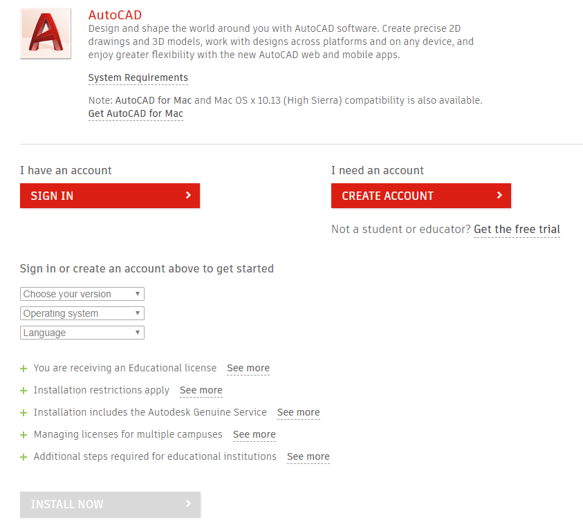
- Install AutoCAD: Ensure you have the latest version of AutoCAD installed on your computer. Autodesk offers various versions tailored to different needs, so choose the one best suited for architectural design and floor planning.
- Set Up Your Workspace: Customize the AutoCAD interface to suit floor planning tasks. Familiarize yourself with the toolbars, command line, and drawing area. Setting up a comfortable workspace can significantly enhance your productivity.
- Understand the Basics: Learn the basic commands and functions of AutoCAD. Commands like LINE, RECTANGLE, OFFSET, and TRIM are fundamental for drawing floor plans. Knowing how to use these effectively is crucial.
- Define Units and Scale: Before starting your drawing, set the correct units and scale for your project. This ensures your floor plan accurately reflects the dimensions of the space you\"re designing.
- Create a Template: Save time by creating a template with pre-set layers, line types, and architectural symbols. This template can be used as a starting point for all your floor planning projects.
- Start with a Rough Sketch: Begin your floor plan by drawing a rough outline of the space. Use the RECTANGLE and LINE commands to delineate the exterior walls.
- Refine Your Drawing: Once the basic shape is in place, start refining your drawing. Add interior walls, doors, windows, and other structural elements using the commands you\"ve learned.
- Add Details and Annotations: Include furniture, fixtures, and annotations in your floor plan. This not only brings your design to life but also provides valuable information for construction and interior design.
- Utilize Layers: Organize your drawing by using layers to separate different elements of your floor plan. This makes editing, viewing, and printing your drawing much easier.
- Save and Backup Your Work: Regularly save your work to avoid losing progress. Consider using cloud storage or external drives for backups.
By following these steps, you\"ll be well on your way to creating professional-quality floor plans with AutoCAD. Remember, practice is key to mastering any new skill, so don\"t hesitate to experiment with different tools and techniques as you progress.
Setting Up Your Workspace and Units
Properly setting up your workspace and units in AutoCAD is crucial for an efficient floor planning process. This section will guide you through configuring your environment and establishing the right units for your projects.
- Choose the Right Workspace: Start by selecting a workspace that suits floor planning. AutoCAD offers several workspaces; the \"Drafting & Annotation\" workspace is most suitable for this task.
- Configure the Units: Accuracy in measurements is key in floor planning. Use the command \"UNITS\" to open the Drawing Units dialog box. Here, you can set the type of units you\"ll be working with (e.g., architectural, decimal) and specify the precision.
- Set Up the Drawing Limits: Define the boundaries of your drawing area by using the \"LIMITS\" command. This ensures that you work within a predefined space, which can help manage the drawing\"s scale and size.
- Adjust the Grid and Snap Settings: Enabling the grid can help you place objects more precisely. Use the \"GRID\" command to toggle the grid visibility and \"SNAP\" command to adjust the snap settings for easier object alignment.
- Customize Your Toolbars: Tailor the AutoCAD interface by customizing toolbars and ribbons. Include tools that you frequently use in floor planning to streamline your workflow.
- Create Layers: Organize your drawing by setting up layers for different elements of your floor plan (e.g., walls, doors, furniture). Assign colors, line types, and line weights to each layer for clarity.
- Save Your Workspace: Once you have configured your workspace, save it. This allows you to quickly access a pre-set environment tailored to your floor planning needs in future sessions.
With your workspace and units set up, you\"re now ready to begin drawing your floor plan with precision and ease. These initial steps are essential in ensuring your project\"s success from start to finish.

Basic Commands for Floor Plan Drawing
Mastering basic commands in AutoCAD is essential for efficiently creating detailed floor plans. This section introduces key commands and how to use them in your drafting process.
- LINE: The fundamental command for drawing straight lines. Use it to outline the walls of your floor plan. Activate the command by typing \"LINE\" or using the shortcut \"L\" in the command window.
- RECTANGLE: Quickly draw rectangular shapes for rooms or areas within your floor plan. Initiate this command with \"RECTANGLE\" or \"REC\" in the command window.
- CIRCLE: Use this command to add circular elements, such as columns or round tables. Type \"CIRCLE\" or \"C\" to start drawing circles.
- OFFSET: Duplicate lines or shapes at a specified distance, ideal for creating parallel walls. Type \"OFFSET\" or \"O\" and enter the distance.
- TRIM: Remove parts of objects that cross or intersect to clean up your floor plan. Activate it by typing \"TRIM\" or \"TR\".
- EXTEND: Lengthen objects to meet the edges of another object, useful for extending walls to meet other walls. Use \"EXTEND\" or \"EX\" command.
- COPY: Duplicate objects within your drawing. This command is useful for replicating furniture or fixtures. Type \"COPY\" or \"CO\".
- MIRROR: Create a mirrored copy of selected objects, perfect for symmetrical rooms or layouts. Activate with \"MIRROR\" or \"MI\".
- ROTATE: Rotate objects in your plan to align or position them correctly. Use \"ROTATE\" or \"RO\".
- DIMENSION: Add measurements to your floor plan. There are several dimension commands, but you can start with \"DIMLINEAR\" or \"DL\" for linear dimensions.
These basic commands form the backbone of floor plan drawing in AutoCAD. Practice using these commands to become more proficient in drafting precise and accurate floor plans.

Creating External Walls
Creating external walls is a critical first step in designing a floor plan in AutoCAD. This section outlines a step-by-step approach to accurately draw the perimeter of a building or structure.
- Set Up Your Drawing: Begin by ensuring your drawing units and scale are correctly set for architectural design. Use the \"UNITS\" command to open the Drawing Units dialog box and select your preferred measurement system.
- Draw the Boundary: Use the \"RECTANGLE\" command to create the initial boundary of your structure. This serves as a guideline for the external walls. Type \"RECTANGLE\" in the command line, then click in the drawing area to set the first corner point, and specify the opposite corner to complete the rectangle.
- Use the OFFSET Command: To create the thickness of the external walls, use the \"OFFSET\" command. Type \"OFFSET\" in the command line, enter the desired wall thickness (e.g., 6 inches or 150 mm), and select the rectangle you just drew. Click inside or outside the original rectangle to place the offset line, creating the wall\"s thickness.
- Trim and Extend: If your design includes walls that are not perfectly rectangular, use the \"TRIM\" and \"EXTEND\" commands to adjust wall lines where necessary. These tools help in customizing the shape and intersections of walls for more complex designs.
- Add Wall Details: For additional architectural details such as wall recesses or extensions, use the \"LINE\" command to draw these features. Use \"OFFSET\" and \"TRIM\" as needed to integrate these details into the external walls.
- Finalize Wall Profiles: Once the basic wall layout is complete, refine the drawing by adding door and window openings using the \"RECTANGLE\" command. Position these openings accurately within the walls, and use \"TRIM\" to remove the wall sections where doors and windows will be placed.
With the external walls accurately drawn, your floor plan\"s basic structure is established. This foundational step is crucial for the overall accuracy and success of your architectural project in AutoCAD.
_HOOK_
Drawing Internal Walls and Partitions
Drawing internal walls and partitions is a crucial step in defining the layout of your space within AutoCAD. This section will guide you through the process of adding these important elements to your floor plan.
- Plan Your Layout: Before drawing, plan the layout of your rooms and spaces. Consider the function of each area and the flow between them.
- Use the LINE or POLYLINE Command: For straight wall segments, use the \"LINE\" command. For continuous walls with multiple segments, \"POLYLINE\" is more efficient. Type \"LINE\" or \"PL\" in the command line to start.
- Set Wall Thickness: Internal walls may have different thicknesses than external walls. Use the \"OFFSET\" command to create two parallel lines representing each side of the wall. Specify the desired thickness when prompted.
- Create Room Partitions: For partitions that do not extend to the ceiling or are meant to be temporary, use the same \"LINE\" or \"POLYLINE\" commands but adjust your line type or layer to differentiate them from permanent walls.
- Add Doors and Openings: Where internal walls intersect or where rooms require access, use the \"TRIM\" command to create openings for doors. You can draw the door using \"RECTANGLE\" or \"LINE\" commands, then \"TRIM\" the wall where the door will be placed.
- Use Layers for Organization: Assign internal walls and partitions to a specific layer in your AutoCAD drawing. This allows for better organization and the ability to hide or isolate certain elements as needed.
- Refine and Detail: Add architectural details to your walls and partitions, such as baseboards, crown molding, or special finishes. Use additional lines or \"OFFSET\" to represent these features accurately.
By following these steps, you can effectively create internal walls and partitions in your AutoCAD floor plan, bringing clarity and precision to the layout of your designed space.

Adding Doors and Windows
Incorporating doors and windows into your AutoCAD floor plan is crucial for realism and functionality. This step-by-step guide ensures accurate representation of these elements in your designs.
- Identify Locations: First, decide where doors and windows will be placed within the walls. Consider the flow of the space and natural light sources.
- Use the DOOR Command: For doors, AutoCAD has specific commands or blocks that can be used to insert door symbols. If unavailable, draw a simple rectangle where the door will be, then use the \"TRIM\" or \"BREAK\" command to remove the wall section.
- Window Blocks: Similar to doors, windows can be inserted using predefined blocks or by drawing them manually. For a manual approach, draw the outline of the window on the wall and use \"TRIM\" to create an opening.
- Set Sizes: Ensure that the dimensions of doors and windows match real-world sizes. Use the \"DIMLINEAR\" command to add measurements and adjust as necessary.
- Detailing: Add additional details to doors and windows, such as frames or glazing bars, using the \"LINE\" or \"POLYLINE\" commands. Differentiate these elements by adjusting line weights or types.
- Layers and Styles: Assign doors and windows to specific layers. This organization helps in isolating these elements for edits or for creating schedules.
- Refinement: Review door swings and window openings for practicality and compliance with design standards. Adjustments can be made using \"ROTATE\" or by editing the block attributes.
By following these steps, you can add detailed and accurately scaled doors and windows to your AutoCAD floor plan, enhancing both the design\"s aesthetics and functionality.
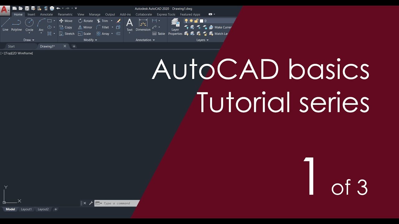
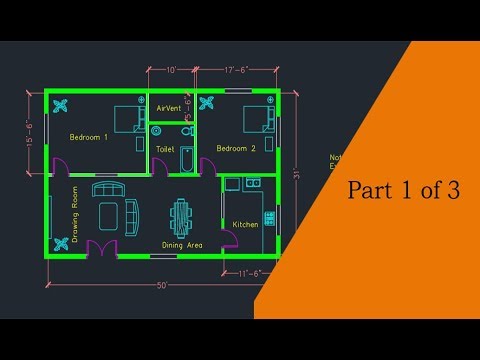
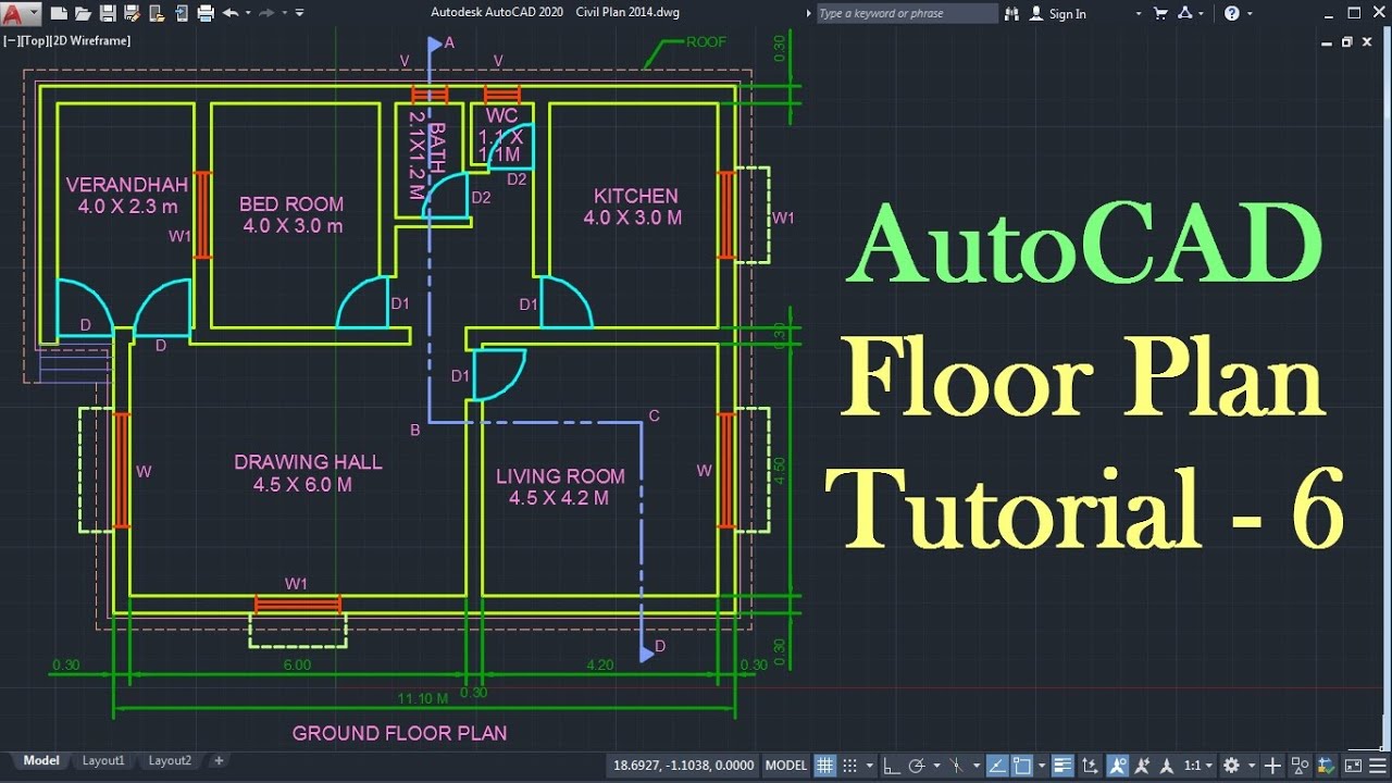
Making a Simple Floor Plan in AutoCAD: Part 1 of 3
Simplify: In this video, we show you how to simplify your life by decluttering your space, organizing your schedule, and minimizing stress. Learn practical tips and tricks to simplify your day-to-day activities and create a more calm and balanced life. Watch now and start simplifying today!
AutoCAD 2D Basics - Tutorial to Draw a Simple Floor Plan: Part 1
Basics: New to the subject? This video provides a comprehensive overview of the basics, breaking down complex concepts into easy-to-understand explanations. Whether you\'re a beginner or need a refresher, this video is perfect for building a solid foundation of knowledge. Watch now and master the basics in no time!
Dimensioning Your Floor Plan
Adding dimensions to your AutoCAD floor plan is a critical step for clarity and construction accuracy. Follow these steps to ensure your dimensions are precise and informative.
- Use the DIMENSION Command: AutoCAD offers various dimensioning tools like linear, aligned, radial, and angular. Start with the \"DIMLINEAR\" for most floor plan dimensions. Access it by typing \"DIMLINEAR\" or selecting it from the dimension toolbar.
- Set Dimension Styles: Before adding dimensions, create or modify a dimension style to match your requirements. Use the \"DIMSTYLE\" command to open the Dimension Style Manager, where you can set text size, arrow styles, and line weights.
- Select the Start and End Points: For linear dimensions, click on the start point of the element you wish to measure, then the end point, and finally, position the dimension line where it\"s clearly readable.
- Dimension Doors and Windows: Place dimensions from the center of doors and windows to the corners of walls to indicate their positions clearly. Use the \"DIMCENTER\" command for center marks.
- Include Room Sizes: Use the \"DIMLINEAR\" command to measure the length and width of each room. Place these dimensions inside the rooms for easy reference.
- Dimension Wall Thickness: Especially for external walls, indicating wall thickness can be crucial. Use the \"DIMLINEAR\" tool to show these measurements on your plan.
- Review and Adjust: After placing all dimensions, review your plan to ensure all necessary dimensions are included and clearly readable. Adjust any overlapping dimensions or unclear labels.
Dimensioning not only aids in the construction process but also helps in conveying the exact sizes of rooms, doors, windows, and other elements in your floor plan. Proper use of dimensioning tools enhances the professionalism and accuracy of your AutoCAD drawings.
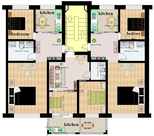
Adding Furniture and Fixtures
Enhancing your AutoCAD floor plan with furniture and fixtures is essential for visualizing the final layout and functionality of a space. This section will guide you through the process of inserting these elements into your design.
- Access AutoCAD Blocks: AutoCAD comes with a library of blocks that represent various pieces of furniture and fixtures. Use the \"INSERT\" command to open the block library and browse through categories like seating, tables, kitchen appliances, and bathroom fixtures.
- Import External Blocks: If the built-in library lacks specific items you need, you can import blocks from external sources. Download blocks from reputable websites or create your own using the \"BLOCK\" command.
- Place Furniture Wisely: When inserting furniture, consider the space\"s flow and functionality. Use the \"MOVE\" and \"ROTATE\" commands to position items accurately within the room, ensuring there\"s enough clearance around each piece.
- Utilize Layers for Organization: Assign furniture and fixtures to their own layer. This not only keeps your drawing organized but also allows you to hide or isolate these elements as needed for clarity.
- Scale Blocks Appropriately: Ensure that the furniture and fixtures are to scale with your floor plan. Use the \"SCALE\" command if adjustments are necessary to fit your design\"s dimensions.
- Detailing and Customization: For a more personalized touch, you can edit blocks to match your specific design needs. Use commands like \"EXPLODE\" to break down a block into editable entities, then modify as needed.
- Label Furniture and Fixtures: Adding labels or tags to your furniture and fixtures can provide useful information about each item. Use the \"MTEXT\" command to add descriptive text or annotations next to your placed objects.
By thoughtfully adding furniture and fixtures to your AutoCAD floor plan, you can create a more detailed and realistic representation of how a space will be used and experienced.
Floor Plan Drawing Techniques and Tips
Creating an effective floor plan in AutoCAD requires both technical skill and creative thinking. Here are some essential techniques and tips to help you develop detailed, accurate, and visually appealing floor plans.
- Start with a Clear Concept: Before you begin drawing, have a clear idea of the space\"s layout, function, and requirements. Sketching out your ideas on paper can be a helpful preliminary step.
- Utilize Layers: Organize your drawing by using layers for different elements (e.g., walls, doors, windows, furniture). This will make it easier to edit specific parts of your floor plan without affecting others.
- Make Use of Blocks: For common elements like furniture, fixtures, and even room layouts, create or download blocks. Blocks save time and ensure consistency across your drawings.
- Apply Accurate Scaling: Ensure that all elements in your floor plan are drawn to scale. This accuracy is crucial for the plan to be a reliable reference for construction or remodeling.
- Pay Attention to Detail: Adding details, even in a basic floor plan, can provide a more comprehensive understanding of the space. Consider including dimensions, labels, and notes.
- Use the Right Tools for the Job: Familiarize yourself with AutoCAD\"s drawing and editing tools. Knowing when and how to use tools like OFFSET, TRIM, EXTEND, and MIRROR can significantly enhance your efficiency.
- Keep It Clean and Readable: Avoid cluttering your floor plan with too much information. Use symbols and labels clearly and keep the drawing as simple as possible for readability.
- Review and Revise: Always take the time to review your floor plan for errors or improvements. Getting feedback from others can also provide new insights.
- Stay Updated with AutoCAD Features: AutoCAD regularly updates its features and tools. Staying informed about these updates can help you take advantage of new functionalities that can improve your floor plans.
By following these techniques and tips, you can refine your approach to floor plan drawing in AutoCAD, leading to better organized, more accurate, and visually appealing designs.
_HOOK_
READ MORE:
Finalizing and Exporting Your Floor Plan
Finalizing your AutoCAD floor plan and preparing it for presentation or construction is a critical phase of the design process. This section provides a step-by-step guide to ensure your floor plan is professional, polished, and ready for export.
- Review Your Design: Thoroughly check your floor plan for any inaccuracies or missing elements. Ensure that all dimensions are correct and that the design meets the project requirements.
- Adjust Line Weights and Styles: Use different line weights and styles to differentiate between various elements of your floor plan, such as walls, doors, and furniture. This enhances readability and visual appeal.
- Add Text and Annotations: Include necessary labels, room names, dimensions, and any other annotations that will make your floor plan informative and easy to understand.
- Clean Up the Drawing: Remove any unnecessary lines, blocks, or elements that are not part of the final presentation. Use the \"PURGE\" command to clean up unused layers and blocks from your drawing.
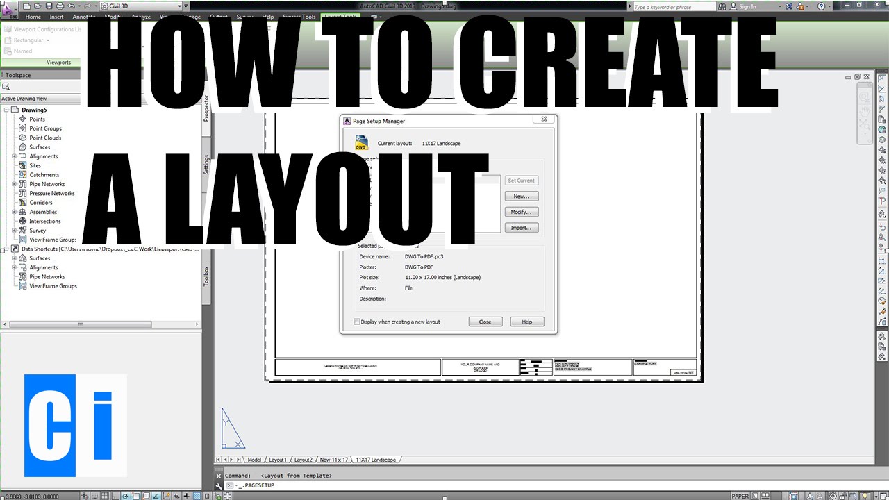
- Layout and Title Block: Prepare a layout view with a title block that includes information about the project, scale, designer, and any other relevant details. This is essential for professional presentations and documentation.
- Save Your Work: Ensure that you save your final design in the AutoCAD drawing file format (.dwg). It\"s also a good practice to save a backup copy.
- Export Your Floor Plan: Export your floor plan to the desired file format, such as PDF or JPEG, for easy sharing and printing. Use the \"EXPORT\" command or the \"PLOT\" command for PDF exports to ensure high-quality outputs.
Following these steps will help you finalize and export your floor plan efficiently, making it ready for client presentations, construction teams, or personal archives.
Embrace the power of AutoCAD to bring your architectural visions to life. With these tutorials, you\"re well-equipped to create detailed and accurate floor plans, enhancing your design skills and project outcomes.