Topic autocad tutorial floor plan: Unlock the secrets of creating detailed floor plans in AutoCAD with our comprehensive tutorial. Designed for beginners and professionals alike, this guide will walk you through the essential steps and techniques to master precision drafting and bring your architectural visions to life.
Table of Content
- How to create a floor plan in AutoCAD?
- Getting Started with AutoCAD for Floor Plans
- Setting Up Your Workspace and Units
- Drawing External Walls Using Commands
- Creating Internal Walls and Partition Layouts
- Adding Doors, Windows, and Furniture to Your Floor Plan
- Dimensioning Your Floor Plan Accurately
- YOUTUBE: Making a simple floor plan in AutoCAD - Part 1
- Utilizing Layers for Efficient Design Workflow
- Applying Text and Annotations for Clarity
- Finalizing Your Floor Plan with Plotting and Printing Tips
- Advanced Techniques: Elevations, Sections, and Detail Drawings
- Resources for Further Learning and Practice Projects
How to create a floor plan in AutoCAD?
To create a floor plan in AutoCAD, you can follow the steps below:
- Open AutoCAD software on your computer.
- Create a new drawing file by clicking on the \"New\" button or using the \"Ctrl + N\" shortcut.
- Set the units of measurement for your drawing by clicking on the \"Format\" menu and selecting \"Units\". Choose the appropriate units for your floor plan.
- Start by drawing the outer walls of your floor plan. Use the \"Line\" command by typing \"L\" on the command line or clicking on the \"Line\" button. Click on one corner of the wall and then click on the opposite corner to create a line. Repeat this for all the walls of your floor plan.
- Use the \"Offset\" command to create wall thickness if needed. Type \"O\" on the command line or click on the \"Offset\" button. Specify the distance for the offset from the existing walls and then click on the inner side of the walls to create the offset lines.
- Add doors and windows to your floor plan using the \"Rectangle\" command or the \"Circle\" command. Draw rectangles or circles at appropriate locations for doors and windows.
- Create interior walls by repeating steps 4 and 5.
- Label rooms and add other annotations by using the \"Text\" command. Type \"T\" on the command line or click on the \"Text\" button. Specify the insertion point for the text and type the desired room name or annotation. You can also adjust the text height, font, and other properties.
- Apply hatching to represent different materials or textures. Use the \"Hatch\" command by typing \"H\" on the command line or clicking on the \"Hatch\" button. Select the desired pattern from the hatch pattern list and then select the areas to be hatched.
- Save your floor plan by clicking on the \"Save\" button or using the \"Ctrl + S\" shortcut. Choose a location and name for your file.
- You can print or export your floor plan as an image or PDF file using the \"Plot\" command or by clicking on the \"Print\" button. Adjust the settings as needed and then select the desired printer or file format.
By following these steps, you can create a floor plan in AutoCAD.
READ MORE:
Getting Started with AutoCAD for Floor Plans
Welcome to the exciting world of AutoCAD floor planning! This section is designed to help beginners familiarize themselves with the basics of AutoCAD for creating detailed and accurate floor plans. We\"ll cover everything from setting up your workspace to finalizing a basic floor plan.
- Setting Up Your Workspace: Start by opening AutoCAD and setting up your workspace. Choose a template that suits floor planning, typically one with architectural units.
- Understanding the Interface: Familiarize yourself with the AutoCAD interface, including the ribbon, toolbars, command line, and properties palette. This knowledge will streamline your drawing process.
- Configuring Units and Scale: Before you start drawing, set the correct units and scale for your project. This ensures that your floor plan is accurately represented and properly scaled.
- Drawing External Walls: Use the LINE or RECTANGLE command to draw the external walls of your plan. Pay attention to the thickness of the walls, which can be adjusted using the OFFSET command.
- Creating Internal Walls: Similar to external walls, use the LINE command to draw internal walls. Use the TRIM and EXTEND commands to neatly join walls.
- Adding Doors and Windows: Insert doors and windows by drawing their outlines or using blocks. Position them accurately within walls using commands like MOVE and ALIGN.
- Placing Furniture: Use the INSERT command to add furniture to your floor plan. AutoCAD’s extensive library offers a variety of furniture blocks to choose from.
- Dimensioning: Use the DIMENSION command to add dimensions to your floor plan. This helps in understanding the space and layout more clearly.
- Layers: Organize your drawing by using layers. Assign elements like walls, doors, windows, and furniture to different layers to keep your drawing organized.
By following these steps, you\"ll be well on your way to creating your first floor plan in AutoCAD. Remember, practice is key to mastering AutoCAD, so don\"t hesitate to experiment with different commands and tools as you learn.
Setting Up Your Workspace and Units
Properly setting up your workspace and units is crucial for creating accurate and professional floor plans in AutoCAD. This section will guide you through configuring your drawing environment to ensure that your designs are precise and to scale.
- Choose the Right Template: Start by selecting an architectural template when you create a new drawing. These templates are pre-configured with the right settings for floor planning.
- Set Drawing Units: Use the \"UNITS\" command to open the Drawing Units dialog box. Here, you can set your units to architectural or metric, depending on your project\"s requirements.
- Adjust Drawing Limits: Set the drawing limits by using the \"LIMITS\" command. This defines the working area of your drawing, ensuring that all elements fit within the designated space.
- Grid and Snap Settings: Configure your grid and snap settings to simplify the placement and alignment of objects. Enable the grid for a visual reference of scale and distance, and adjust snap settings for precise cursor movement.
- Layer Management: Organize your drawing by setting up layers for different elements such as walls, doors, windows, and furniture. Assign colors, linetypes, and lineweights for each layer to maintain clarity and order in your design.
- Customize the Workspace: Tailor the AutoCAD interface to suit your workflow by customizing the ribbon, toolbars, and palettes. Save your workspace so you can easily access your preferred setup in future projects.
- Save Frequently Used Blocks: For efficient floor planning, save blocks of common elements like furniture and fixtures in a tool palette for quick insertion into your drawings.
By carefully setting up your workspace and units, you\"re laying a solid foundation for efficient and accurate floor plan creation in AutoCAD. Remember, a well-organized workspace significantly enhances your drafting productivity and precision.

Drawing External Walls Using Commands
Creating external walls is a foundational step in drafting a floor plan in AutoCAD. This section will guide you through using specific commands to draw precise and to-scale external walls for any project.
- Starting the Line Command: Activate the LINE command by typing \"LINE\" in the command line or by selecting it from the toolbar. This command allows you to draw straight lines, which are essential for external wall outlines.
- Specifying the First Point: Click in the drawing area or enter coordinates to specify the starting point of your wall.
- Drawing the Wall: Move the cursor to draw the wall in the desired direction. Enter the length of the wall manually or by clicking a second point in the drawing area.
- Using the Offset Command: To create walls with thickness, use the OFFSET command. Specify the distance that represents the thickness of your walls (e.g., 6 inches or 150mm) and select the line you’ve just drawn. Click inside or outside the original line to place the parallel wall line.
- Creating Corners: Repeat the LINE and OFFSET commands to draw the perimeter of the building. Use the \"FILLET\" command with a radius of 0 to create sharp corners where walls meet.
- Closing the Loop: Ensure all external walls are connected to form a closed loop. This is crucial for defining the outer boundary of your floor plan accurately.
With these steps, you\"ll be able to efficiently draw the external walls of your building in AutoCAD, forming a solid base for your floor plan design. Remember to frequently save your work and to utilize layers for better organization and editing capabilities.

Creating Internal Walls and Partition Layouts
After setting up external walls, the next step in your floor plan is to design internal walls and partitions. This section will guide you through the process of creating these elements to effectively divide the space into rooms and areas.
- Planning Your Layout: Before you start drawing, plan the layout of your internal walls. Consider the function of each room, the flow of movement, and the need for privacy or open spaces.
- Using the Line Command: Similar to external walls, use the LINE command to draw internal walls. Begin by specifying the start and end points of each wall segment. For complex layouts, consider using the POLYLINE command for continuous walls.
- Setting Wall Thickness: Apply the OFFSET command to give your internal walls thickness. A common practice is to make internal walls thinner than external ones, so adjust the offset distance accordingly.
- Creating Doorways: Doorways can be created by leaving gaps in walls or by using the TRIM command to remove sections of the wall where doors will be placed. Ensure doorways are wide enough for accessibility.
- Adding Partitions: For areas that require partitioning without full walls, use the LINE or POLYLINE commands to draw partial wall segments. These can be used to indicate room dividers or cubicle walls in office layouts.
- Utilizing Layers: Organize your internal walls and partitions on separate layers from external walls and other elements. This allows for easy editing and adjustments as your design progresses.
- Checking Room Sizes: Use the DISTANCE or AREA commands to check the sizes of rooms and ensure they meet your requirements or regulatory standards.
With careful planning and precise command use, you can create a detailed and functional internal layout for your floor plan. Remember, the internal structure of your design plays a crucial role in the overall functionality and aesthetic of the space.
_HOOK_
Adding Doors, Windows, and Furniture to Your Floor Plan
Adding doors, windows, and furniture to your AutoCAD floor plan brings your design to life, providing a realistic and functional layout. Follow these steps to incorporate these essential elements into your plan.
- Inserting Doors:
- Use the DOOR command or select a door block from the tool palettes. Place the door on an appropriate wall, ensuring it opens in the correct direction.
- Adjust the door size and swing by modifying the block attributes, if necessary.
- Placing Windows:
- Choose a window block from the tool palettes or use the WINDOW command. Position the windows along external walls, considering natural light and ventilation.
- Ensure window heights and sill levels are consistent and appropriate for the room\"s use.
- Adding Furniture:
- Navigate to the DesignCenter or tool palettes to find furniture blocks that suit your floor plan. Common elements include sofas, tables, beds, and chairs.
- Place the furniture carefully to optimize space usage and traffic flow within the room.
- Customizing Your Design:
- Use the SCALE and ROTATE commands to adjust the size and orientation of doors, windows, and furniture to fit your design precisely.
- Consider the use of layer management to organize your elements effectively, making it easier to edit and update your design.
- Reviewing Your Layout:
- Once all elements are added, take a step back and review your layout. Ensure that doors and windows do not obstruct furniture and that the space feels balanced and functional.
- Use the MEASUREGEOM command to verify distances and clearances, ensuring that your design adheres to building codes and standards.
By carefully adding doors, windows, and furniture to your floor plan, you can create a detailed and realistic representation of your design vision, showcasing how the space will be used and experienced.

Dimensioning Your Floor Plan Accurately
Accurate dimensioning is crucial for the success of any floor plan. It ensures that the plan is practical, conforms to building codes, and communicates the design intent clearly to clients and contractors. Follow these steps to dimension your floor plan effectively in AutoCAD.
- Understanding Dimension Styles:
- Before you start, familiarize yourself with the different dimension styles available in AutoCAD. Use the DIMSTYLE command to create or modify a dimension style that suits your project requirements.
- Adding Linear Dimensions:
- Use the DIMLINEAR command to add linear dimensions to your floor plan. Select the start and end points of the element you wish to measure, and then place the dimension line.
- Dimensioning Doors and Windows:
- For doors and windows, use the DIMCONTINUE command to create a series of dimensions that share a common extension line. This helps in displaying the distances between openings clearly.
- Using Angular Dimensions:
- Where necessary, apply angular dimensions to indicate the angles between walls using the DIMANGULAR command. This is particularly useful for non-orthogonal walls.
- Area Dimensions:
- To specify the area of rooms, use the AREA command followed by the ADD option. This can help in calculating material estimates and ensuring space efficiency.
- Checking Dimensions:
- After adding all necessary dimensions, double-check them for accuracy. Ensure that all dimensions are clearly legible and do not overlap with other elements in the floor plan.
- Finalizing Dimension Placement:
- Adjust the placement of dimension texts and lines as needed for clarity and readability. Use the DIMEDIT and DIMTEDIT commands to edit dimension texts and lines, respectively.
By carefully dimensioning your floor plan, you ensure that it accurately represents the designed space, adheres to the necessary standards, and facilitates smooth execution during construction.
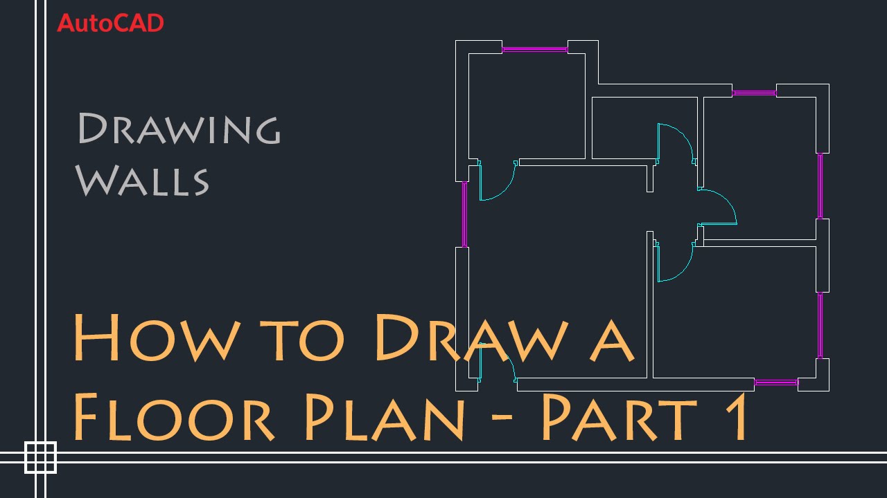
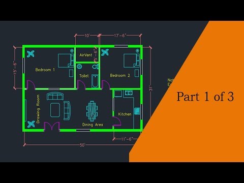
Making a simple floor plan in AutoCAD - Part 1
\"Discover the endless possibilities of AutoCAD and unlock your creativity with our video tutorial! Learn how to design stunning 2D and 3D models like a pro, from architectural masterpieces to intricate mechanical drawings. Don\'t miss out on this opportunity to take your drafting skills to the next level!\"
AutoCAD Floor Plan Tutorial
\"Dreaming of the perfect floor plan for your new home? Look no further! Our video will guide you through the process of creating a functional and aesthetically pleasing layout. From selecting the right furniture placement to optimizing natural lighting, we have all the tips and tricks to help you design the home of your dreams!\"
Utilizing Layers for Efficient Design Workflow
Layers in AutoCAD are a powerful tool for organizing different elements of your floor plan, making the design process more efficient and the drawings easier to manage and edit. Here’s how to effectively use layers in your floor plan projects:
- Understanding Layers:
- Think of layers as transparent sheets stacked on top of each other, where each sheet represents a different category of your drawing, such as walls, doors, windows, and furniture.
- Creating and Naming Layers:
- Use the LAYER command to open the Layer Properties Manager. Create new layers for each category of your drawing and give them meaningful names for easy identification.
- Assigning Colors and Linetypes:
- Assign different colors and linetypes to each layer. This not only helps in distinguishing between different types of elements but also makes your drawings more readable.
- Using Layers for Editing:
- By placing elements on separate layers, you can easily hide or lock layers to focus on specific parts of your design, simplifying the editing process.
- Layer States:
- Save and restore different layer states to quickly switch between various views of your project, facilitating presentations or focused work on different aspects of your design.
- Plotting with Layers:
- Control which layers appear in your final plotted drawing by freezing or turning off layers that you do not want to print, ensuring that your printed plans are clear and focused on the relevant details.
Mastering the use of layers in AutoCAD streamlines your workflow, enhances the clarity of your floor plans, and contributes significantly to the efficiency of your design process.
Applying Text and Annotations for Clarity
Text and annotations are essential in AutoCAD floor plans to convey detailed information clearly and accurately. They help in identifying room names, dimensions, material specifications, and other critical data. Here\"s how to effectively apply text and annotations:
- Using the Text Command:
- Select the TEXT command for short, single-line text entries, such as room names or labels. Choose a point in your drawing, specify the text height, and then type your text.
- Applying Multiline Text:
- For longer text blocks, like descriptions or notes, use the MTEXT command. This opens an editor that allows for text formatting and column management.
- Dimensioning for Clarity:
- Ensure all measurements are clearly annotated with the DIMENSION command. Use leader lines (LEADER command) to point to specific features or notes, adding clarity without cluttering the drawing.
- Creating Annotations:
- Annotations, including door numbers, window types, and equipment labels, can be added using the ANNOTATE tab. These annotations can be standardized across projects using styles.
- Layer Management for Text and Annotations:
- Place text and annotations on separate layers from the drawing elements. This practice allows you to easily show or hide text for different presentation needs.
- Using Tables:
- For complex data, such as a window schedule or room finishes, use the TABLE command to organize information in a structured and readable format.
By thoughtfully applying text and annotations, your floor plan will communicate more than just spatial layouts; it will provide a comprehensive guide to the design intentions, specifications, and details necessary for accurate construction and interpretation.
Finalizing Your Floor Plan with Plotting and Printing Tips
Finalizing and printing your AutoCAD floor plan accurately is crucial for ensuring that the design is communicated clearly and effectively. Here are some essential tips for plotting and printing your floor plan:
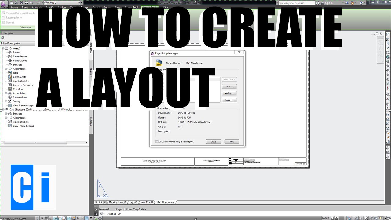
- Setting Up the Plot:
- Open the Page Setup Manager and select a layout. Configure your plot settings, including the printer/plotter, paper size, and plot area. Choose the scale of your drawing accurately to ensure that your plan prints at the correct size.
- Choosing the Right Scale:
- Ensure the scale of your drawing matches the standard architectural or engineering scales. This is crucial for maintaining the accuracy of your design when printed.
- Using Viewports:
- In layout view, use viewports to control the portions of your drawing that are visible on the page. This allows for detailed sections or multiple views of the plan to be presented clearly.
- Checking Layer Visibility:
- Before plotting, ensure that all necessary layers are visible and unnecessary layers are turned off or frozen. This step is essential for a clean and focused printout.
- Previewing Before Printing:
- Always use the Plot Preview feature to check for any issues with scale, layer visibility, or alignment before sending your drawing to print. This can save time and resources by avoiding reprinting.
- Selecting Quality and Color:
- Adjust the print quality settings based on your needs. For final presentations, use higher quality settings. Also, decide if you need a color or monochrome print, depending on the purpose of your floor plan.
- Saving Plot Settings:
- After configuring your plot settings for a project, save them as a page setup. This allows you to easily reuse the same settings for future plots, ensuring consistency across your documents.
By following these tips, you can ensure that your floor plan is printed accurately and professionally, making it a valuable tool for presentations, construction, and documentation.
_HOOK_
Advanced Techniques: Elevations, Sections, and Detail Drawings
Once you have mastered the basics of floor planning in AutoCAD, you can enhance your architectural drawings with elevations, sections, and detailed drawings. These advanced techniques provide a more comprehensive view of your design, showcasing it from different perspectives and detailing specific components. Here’s how to approach each element:
- Creating Elevations:
- Use the VIEWBASE command to generate elevations from your 3D model or draw them manually by projecting the vertical faces of your design onto a 2D plane.
- Detail the exterior finishes, window styles, and door heights to give a clear understanding of the building facade.
- Drawing Sections:
- Sections are cut through the structure to show internal features. Use the SECTIONPLANE command to create a section plane in your model, then generate a section view.
- Highlight key structural elements, material layers, and interior spaces that are not visible in floor plans or elevations.
- Developing Detail Drawings:
- Detail drawings focus on specific aspects of your design, such as custom joinery, intricate architectural details, or construction techniques.
- Use the SCALE command to draw these elements at a larger scale, ensuring that every detail is clearly represented.
- Annotation and Dimensioning:
- Apply annotations and dimensions to your elevations, sections, and detail drawings for clarity. Include material specifications, finish types, and assembly instructions.
- Utilizing Layers:
- Organize your advanced drawings on separate layers from the floor plan. This keeps your project file organized and makes it easier to manage different views of your design.
By incorporating these advanced techniques into your AutoCAD projects, you can produce a more detailed and complete set of architectural drawings. This not only helps in conveying your design intent but also in facilitating a smoother construction process.
READ MORE:
Resources for Further Learning and Practice Projects
Enhancing your AutoCAD skills requires continuous learning and hands-on practice. Below is a curated list of resources that offer comprehensive tutorials, practice projects, and insights into advanced AutoCAD techniques. Whether you\"re a beginner looking to solidify your fundamentals or an experienced user aiming to master sophisticated tools, these resources will support your journey.
- AutoCAD Official Training Guides: Autodesk offers a variety of training guides and manuals that cover everything from basic operations to advanced modeling techniques.
- Online Course Platforms: Websites like Udemy, Coursera, and LinkedIn Learning provide in-depth AutoCAD courses taught by industry professionals.
- YouTube Tutorials: Channels dedicated to AutoCAD training offer free, visual learning resources that cover a wide range of topics.
- AutoCAD Blogs and Forums: Engaging with the AutoCAD community through blogs and forums can provide valuable insights, tips, and solutions to common challenges.
- Practice Projects: Applying your skills to real-world projects is crucial. Start with simple floor plans and gradually move to more complex designs that incorporate elevations, sections, and details.
- Books and eBooks: There are numerous books and eBooks available that cater to all levels of AutoCAD users, offering tutorials, tips, and project ideas.
- AutoCAD Libraries and Block Databases: Utilize libraries and block databases to enhance your drawings and increase efficiency.
By leveraging these resources, you can continue to develop your AutoCAD proficiency, stay updated with the latest features and tools, and take your design skills to the next level.
Embarking on your AutoCAD journey with this comprehensive guide ensures a solid foundation in creating floor plans. Harness these skills to bring architectural visions to life, and stay curious as there’s always more to learn and explore in the vast world of design.